TE�MINAL
L
_
__j
T�AN SFORME:R COIL
FRONT
VIEW
2-D-1488
Fig.
J l.
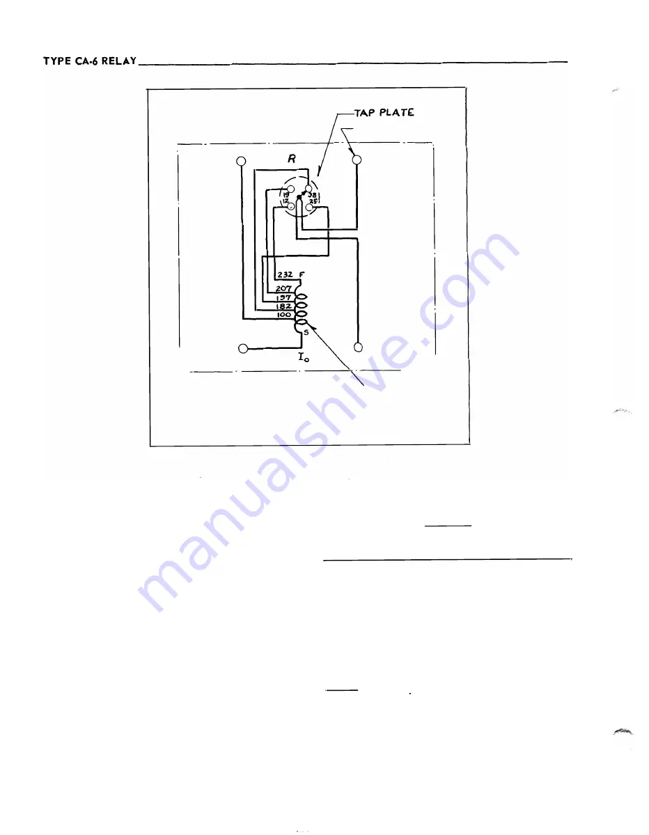
Internal Wiring D iagram of the A uxiliary C urrent Transformer.
CONN E CTIONS
One relay per phase is normally recommended for
the protection of buses with up to
8
"equivalent cir
cuit" connections. An "equivalent circuit" is de
fined as major source or a group of feeder circuits.
The grouped feeder circuits• fault contribution should
not exceed 5% of the total phase or ground fault cur
rent , with normal bus connections.
In paralleling
current transformers for the feeder group or groups,
the load current distribution should be examined to
insure that the
1 0
ampere continuous rating of the
relay restraint windings is not exceeded.
The recommended connections are outlined in
Table I.
10
TAB L E I
Total No.
No. of Feeder
Case
of Eq. Ckts.
Groups
Connections
I
3
Q-
2
Fig.
6
n
4
Q-3
Fig.
6
III
5
0-1
Note
1
IV
5
2-4
Fig. 7
v
6
0-1
Note
1
VI
6
2-5
Fig. 7
vn
7
0-6
Note
1
VIII
8
o-7
Note
1
Note
1
-
-
Same as
4
circuit bus of Fig.
6
except
parallel CT's in pairs.
(1
set in parallel for 5 ckt.
bus,
2
for
6
ckt. bus, etc.)
www
. ElectricalPartManuals
. com


