T Y P ES CA- 1 6 AND CA-26
R
ELAYS
�,
CHANGE
SCALE
0
�1-
0
CA-26
0
0
0
I
� '
0
0
0
0
2
4
6
8
10
30
'0
70
90
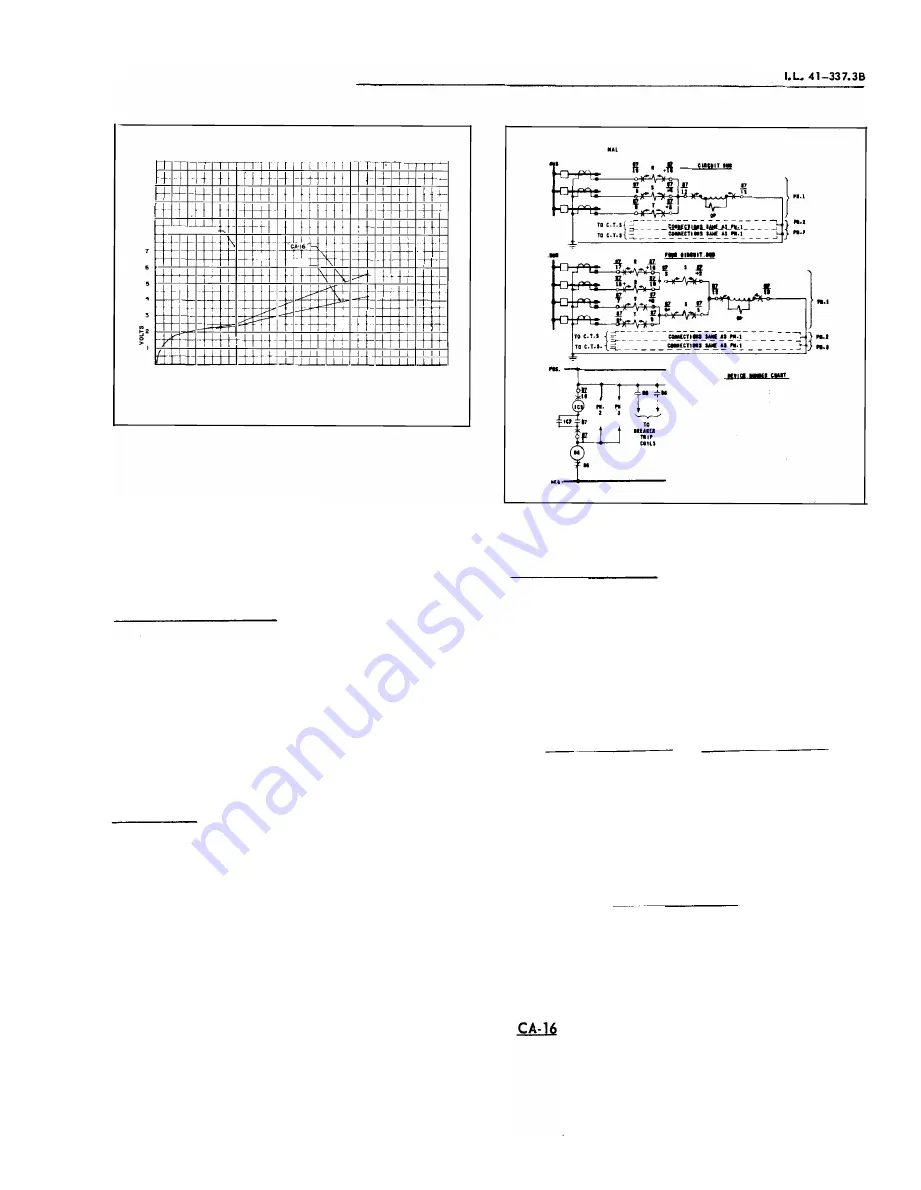
OPERATING CURRENT IN AMPERES
Curve 537957
Fig.
7.
Typical B urden C haracteristic of the Operating
Circuit of the CA- 1 6 and CA-26 D ifferential R e
lays
would ever be expected from a consideration of the
usual
ratio c urve s of the current transformers in
volved.
The time of operation of the relays is shown in
Figure
6.
C A- 2 6 T r a n sfor m e r
R e l ay
The typ e CA-
26
transformer differential relay in
cludes an indicating instantaneous trip unit (see Fig.
4) , which operates on internal faults. The instanta
neous unit should have a s etting e qual to the maxi
mum rms symmetrical external fault current. Such a
s etting will prevent operation of the instantaneous
unit when a current transformer is severely saturated
by the d-e component of an asymmetrical external
fault current.
T r i p C ir c u i t
The main contacts will safeiy close
3 0
ampere s
at
250
volts d-e and the seal-in c ontacts of the in
dicating contactor switch will s afely car ry this c ur
rent long enough to trip a circuit bre aker.
The indic ating instantaneous trip contacts will
safely close
30
amperes at
250
volts d-e, and will
c arry this current long enough to trip bre aker.
The indic ating contactor switch has two tap s that
provide a pick-up setting of
0 . 2
or 2 ampere s . To
change taps re quires connecting the le ad located
in
front of the tap block to the desired setting by means
of a screw connection.
EXTEit
'SCHEMAliC Of OlE 'SET Of TYP'£ CA-10 JfElATS
FOit
THE PROTECT lOt Of
• TMIU: AID fOUl Ct ftC\11
T
IUS
TMIIE
11
•
l't:K£11
..
[
DlffU(ITIAL
IIUf,tnl
g...tl
ICI
•
IUIUTIH
CIITACTII
•tTU
)
tf''
..
lfOATIII
Ctll
(lin
..
L.ll.
II.IJDt)
II
I
• P111(D
IISTUIIT CIIL
""
(IOniM
1.11.
£\DIUT)
16-ll
I
•
NIIEI IISTUtn
CIIL
RUt
(Ttr L•I· IU.IT)
T
•
.PUUI IIITUIO
CIIL
(Ttrl.t. I�IT)
II•
Wlli.IIY Tl"tiH
IUU, T"l
&
187A424
Fig.
8.
External Schematic of the Type CA-1 6 Relays for
Three and Four Circu it B u s Protection
T r i p C i r c u i t C o n s t a nts
Indi.cating Contactor Switc h (ICS)
0. 2
ampere tap
2.0
ampere tap
6 . 5
ohms d-e resistance
0.
15 ohms d-e resistance
E N E R G Y R E Q U I R E M E N T S
Burden of each restraint coil at
5
amperes
VOLT AMPERES
. 75
Continuous Rating
1 second rating
Burden of operating circuit
POWER FACTOR
. 7
14 amperes
4 60 amp eres
VOL T AMPERES
Variable (See Fig.
7)
Continuous rating
8
amperes
1 second rating
280
amperes
C O N N E C T I O N S
To determine the a-c connections , id entify each
5
www
. ElectricalPartManuals
. com


