background image

4 of 8

ISSUED: 01-17-06  SHEET #: 202-9091-1

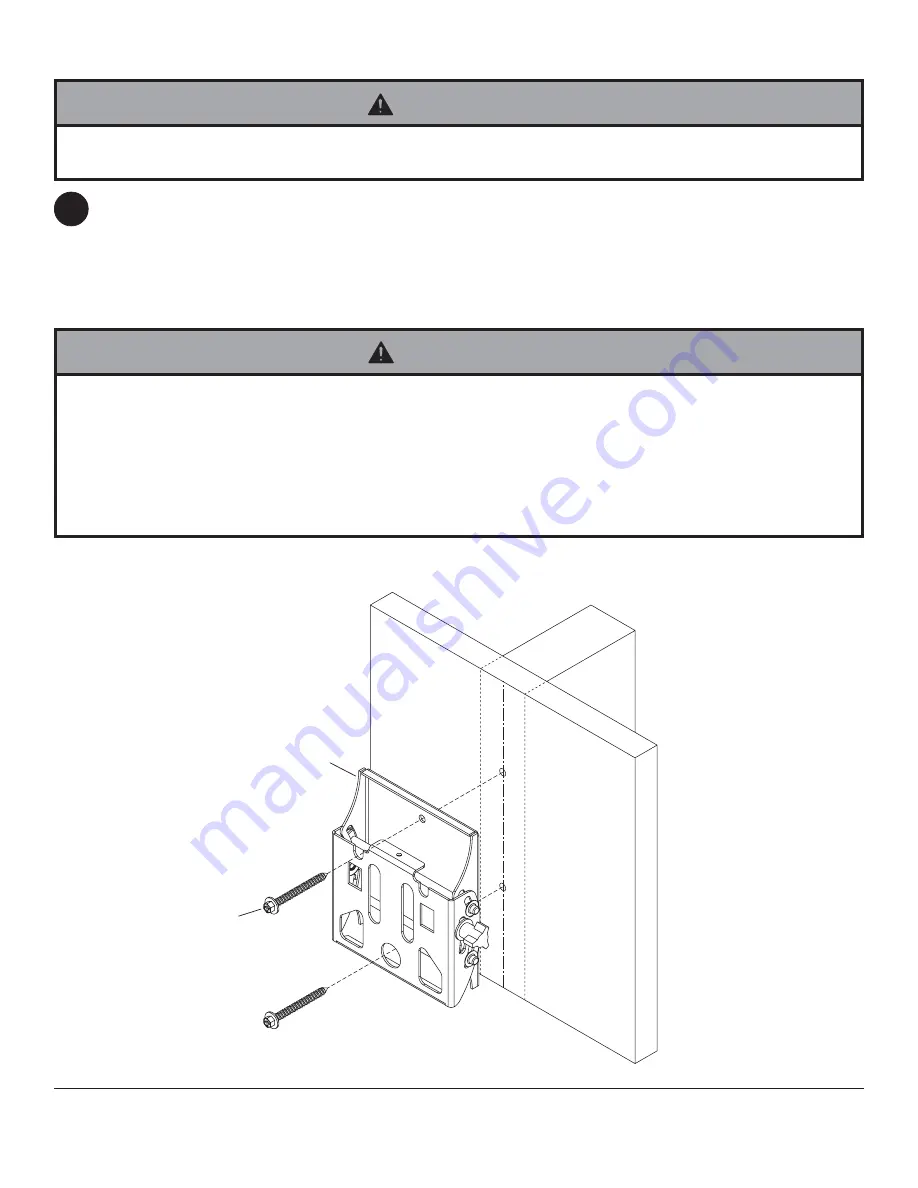
Installation to Single Wood Stud Wall

1

Use a stud finder to locate the edges of the stud. Use of an edge-to-edge stud finder is highly recommended. Based
on its edges, draw a vertical line down the stud’s center. Place tilt assembly (

B

) on wall as a template, making sure

that the two mounting holes are over the stud centerline. Level tilt assembly, and mark the center of the two holes.
Drill two 5/32" (4 mm) dia. holes 2-1/2" (65 mm) deep. Make sure that the tilt assembly is level, secure it using two
#14 x 2-1/2" wood screws (

G

) as shown.

Skip to step 2 on page 6.

• Make sure that the wall will safely support the combined load of the equipment and all attached hardware and

components.

WARNING

• Tighten wood screws so that tilt assembly is firmly attached, but do not overtighten. Overtightening can damage the

screws, greatly reducing their holding power.

• Never tighten in excess of 80 in. • lb (9 N.M.).

• Make sure that mounting screws are anchored into the center of the stud. The use of an "edge to edge" stud finder is

highly recommended.

• Hardware provided is for attachment of mount through standard thickness drywall or plaster into wood studs. Installers

are responsible to provide hardware for other types of mounting situations.

WARNING

G

B

Summary of Contents for MT80A TILT

Page 1: ...tioning and adjustment of the screen Installation and Assembly Universal Tilt Wall Mount for 15 37 Screens Model MT80A TILT R This product is intended for use with UL Listed products and must be insta...

Page 2: ...care at 1 866 287 5555 This product should only be installed by a qualified professional Make sure that the wall will safely support the combined load of the equipment and all attached hardware and co...

Page 3: ...095 4346 B tilt assembly 1 095 0360 C Alligator anchor 2 590 0097 D M4 x 10 mm phillips screw 4 504 9012 E M4 x 20 mm phillips screw 4 504 9020 F retaining spacer 4 590 5005 G 14 x 2 1 2 hex head woo...

Page 4: ...o 14 x 2 1 2 wood screws G as shown Skip to step 2 on page 6 Make sure that the wall will safely support the combined load of the equipment and all attached hardware and components WARNING Tighten woo...

Page 5: ...ensity minimum Lighter density concrete may not hold concrete anchor Make sure that the wall will safely support the combined load of the equipment and all attached hardware and components WARNING CUT...

Page 6: ...ocket attach adapter plate A to back of screen using four M4 x 20 mm screws E and four retaining spacers F as indicated below Attaching Adapter Plate to Flat Panel Screen If screws don t get three com...

Page 7: ...an cause damage to mount Tighten screws to 20 in lb 2 26 N M maximum torque CAUTION WARNING fig 3 Adjust tension knob on right side of mount shown in figure 4 to desired tension to balance your screen...

Page 8: ...mage caused by a service or repairs by anyone other than personnel authorized by Westinghouse Digital Electronics b the failure to utilize proper packing when returning the product c improper installa...

Reviews: