S I MPLE TRANSFORMER
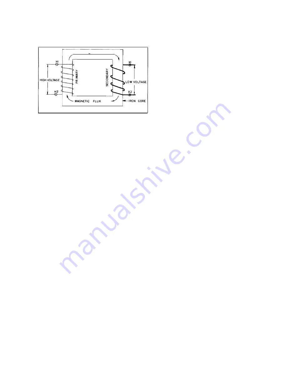
Fig. 1 7
7.2 Operation Instructions
This power transformer was built in accordance with the
American National Standards Institute (ANSI) C.57 . 1 2 ,
series o f standards. I t will perform a s designed if i t is op
erated in accordance with the applicable standards, which
include:
General requirements for distribution, power and regu
lating transformers - A.N.S.I. C .5 7 . 1 2 .00.
Requirements for transformers 1 38000 volts and below
5 0 1 through 1 0000/ 1 3333/ 1 6667 Kva, single phase 5 0 1
through 30000/40000/50000 Kva, three phase A.N.S.l.
C.5 7 . 1 2 . 1 0.
Test code for distribution, power and regulating trans
formers - A.N.S.l. C.5 7 . 1 2 .90.
Guide for loading oil immersed distribution and power
t ransformers - A.N.S.I. Appendix C.5 7 . 1 2 .92. (or NEMA
TR 98 )
Follow these guidelines to p revent damage to the t rans
former and to reduce hazard to personnel.
1 . If the applied voltage is 1 05% of the rated voltage
(for example , 1 5 1 20 volts when the tap changer is on the
1 4400 volt position), then the load amperage must be
reduced by 5%. The maximum allowed overvoltage when
the transformer is connected to a load is 5% above rated.
CONNECTION TO A VOLT AGE OTHER THAN THE
RATED TERMINAL-TO-TERMINAL VOLTAGE MAY
DAMAGE THE TRANSFORMER AND CAN C AUSE
INJURY TO PERSONNEL.
2. If the transformer is energized but the secondary is
not connected to a load, the applied voltage should not
25
exceed 1 1 0% of the rated voltage. (For example, 1 5 840
volts when the tap changer is in the 1 4400 volt position).
3 . Transformers depend entirely on the surrounding air
to dissipate heat from the transformer losses. The am
bient should not exceed 40°C ( I 04°F) and the average
temperature of the air for any 24 hour period should not
exceed 30°C (86°F). The dial thermometer should read
less than the sum of the maximum ambient temperature
and the rated temperature rise during normal operation.
That is, the maximum top liquid temperature for a 5 5°C
rise transformer is 95 °C, and 1 05°C for a 65°C rise
transformer . The transformer's useful life will be short·
ened if the transformer is operated with a greater liquid
temperature .
4. The kva capacity of a transformer may be increased by
adding fans to force air over the cooling tubes. The
amount of allowed kva increase is on the transformer
nameplate . It is very important that all fans and fan con
trols be in operating condition and receive the mainte
nance required by Section 8 . 1 . If the fans fail to operate,
the transformer's useful life will be reduced and it may
fail from overheating.
5 . Mount the transformer on a level base so that the in
sulating fluid will circulate through all coolers. If the
transformer has been designed t o allow operation at a
tilt , the nameplate will state the maximum tilt in de
grees. If the maximum design tilt is exceeded, the trans
former may fail immediately because energized parts are
no longer under liquid. The transformer may fail from
overheating if the transformer is mounted at a tilt such
that some coolers are ineffective.
6. Transformer may be connected in parallel if these
conditions are met.
a) Polarity, additive or subtractive must be the same
(single phase transformers).
b) Phase angle shift must be the same (three-phase
transformers). Phase angle shift is shown on the name
plate by the phasor diagram. Refer to Section 5 . 3 .
c ) Phase rotation must be the same. (Three-phase
transformers). The phase rotation is shown on the
nameplate by the phasor diagram. Refer to Section
5 .3 .
d) Transformer turns ratios and voltage ratings must
be the same within 0.5%.


