background image

 6


ENGLISH

QKG06

Web: www.conglom.com/documentation/

Installation (continued)


INSTALLATION OF MOUNTING ASSEMBLY

Top supporting ring

Top supporting ring screw

Fig. 5a

Fig. 5b

Flange

Flange ring

Supporting

plate

Gasket

Plumber’s

Putty

Sink flange

Recommended

Sink

Fig. 7a

Fig. 7b

Supporting

plate

Gasket

Sink
flange

Sink

Fig. 7

NOTE:


Pay close attention how the parts come assembled, as they have been 
correctly assembled by the factory (see Fig. 5). 

This food waste disposer has been designed to operate on 110-120 Volt, 

60 Hz electrical circuit. 


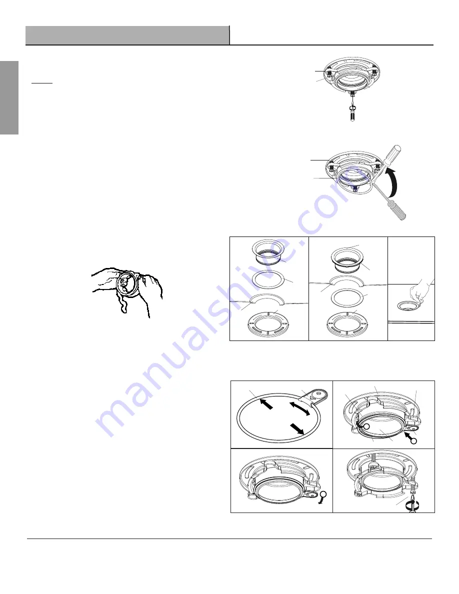
- Disassemble the mounting assembly from the disposer by turning 

the bottom supporting ring clockwise.


- Loosen the 3 screws all the way or remove them from the top 

supporting ring (Fig. 5a), then use a screw driver to remove the 

flange ring (Fig. 5b).


-

The sink flange may be installed with or without use of plumber’s 

putty (see Fig 7 and 7a). 


If you use putty, (see Fig. 7a) form a ring around the underside of 

the sink flange (see Fig. 6). Insert the flange into the sink opening, 

press down hard to squeeze out the excess putty. Trim off excess 
putty from the top and bottom of the sink opening (see Fig. 7b). Do 

not rotate the flange once it is seated.

Fig. 6


-

Use duct tape or place a heavy object on top of the sink flange to 

keep it in place.


-

Stretch the flange ring and insert the ends securely into the ring 

tool. Keep your fingers away from the ends of the flange ring at all 

times (see Fig. 8).


- Insert the supporting plate and the top supporting ring and hold 

them in place. Place the ring tool in the groove of the sink flange 

with the arrow side towards you facing towards the bottom. Using 

your thumb, push the opposite end of the flange ring until it snaps 

into the groove of the sink flange (see Fig. 8a).


- Release the ring tool by rotating it downwards until it snaps away 

from the flange ring (see Fig. 8b).


- Tighten the 3 top supporting ring screws sequentially until the 

flange is very securely fastened to the sink (see Fig. 8c)

Top supporting ring

Ring tool

Supporting plate

Flange ring

Sink flange

Groove of
sink flange

Fig. 8a

1

2

Fig. 8

3

Fig. 8b

Fig. 8c

Ring tool

Flange ring

Top supporting

ring screw

Summary of Contents for QKG06

Page 1: ...Z ITM ART 1600061 QKG06 HIGH TORQUE GARBAGE DISPOSER TRITURADOR DE BASURA DE M XIMO TORQUE 1 1 4 HP OWNER S MANUAL MANUAL DEL USUARIO INSTALLATION VIDEO AVAILABLE VIDEO INSTALLACI N DISPONIBLE WWW CON...

Page 2: ...e manufacturer If you have any questions contact the manufacturer 3 Installation work and plumbing must be done by qualified person s in accordance with all applicable codes and standards 4 When attem...

Page 3: ...use of this product We will not be held liable for inconvenience caused by loss of use of this product costs incurred for labour or materials removal and installation of replacement units or any othe...

Page 4: ...om Supporting Ring F B C E D G Elbow Gasket Discharge Elbow Elbow Flange Screws Part Description Quantity A Stopper 1 B Removable splash guard 1 C Includes Sink flange Rubber sink flange gasket Flange...

Page 5: ...provide additional leverage for turning the mounting ring see Fig 2 Some disposers may require the removal or loosening of nuts from the mounting screws see Fig 3 Some disposers may require the remov...

Page 6: ...sert the flange into the sink opening press down hard to squeeze out the excess putty Trim off excess putty from the top and bottom of the sink opening see Fig 7b Do not rotate the flange once it is s...

Page 7: ...off the elbow gasket from the discharge elbow first then attach the flange to the discharge elbow then reset the elbow gasket see Fig 9a Make sure the elbow gasket is attached to the discharge elbow c...

Page 8: ...that the reset button is readily accessible see Fig 12 Make sure the cushion mount is properly in place Line up the disposer under the mounting assembly Lift and guide the disposer so that all three t...

Page 9: ...the appropriate household current only WARNING Improper connection of the equipment grounding conductor can result in a risk of electric shock Check with a qualified electrician if you are not sure Do...

Page 10: ...hile grinding The disposer is actually increasing torque grinding power and is operating under normal conditions Before turning disposer off let water and disposer run for approximately 15 seconds aft...

Page 11: ...ripped The reset button is red and is located on the front end of the disposer Push the button in until it clicks and remains depressed If the reset button has not been tripped check for a shorted or...

Page 12: ...asket Supporting Plate Top Supporting Ring with 3 screws Flange Ring Cushion Mount C Ring Tool D F Stopper Splash Guard Bottom Supporting Ring Elbow Gasket Discharge Elbow Elbow Flange Screws Part Des...

Page 13: ...pra 2 Use esta unidad nicamente de la manera que fue dise ada por el fabricante Si tiene alguna pregunta p ngase en contacto con el fabricante 3 La instalaci n y plomer a deben estar a cargo de una pe...

Page 14: ...o costos incurridos en mano de obra o materiales retiro e instalaci n de unidades de remplazo ni ning n otro da o incidental o consecuente Costos relacionados con la obtenci n de acceso para la repara...

Page 15: ...ontaje Anillo de soporte inferior B C E F G D Pre instalado en el codo del desag e Junta del codo Codo del desag e Brida del codo Tornillos Parte Descripci n Cantidad A Tap n 1 B Protecci n contra sal...

Page 16: ...proporcionar una palanca adicional para girar el anillo para montura Fig 2 En algunos trituradores es necesario quitar o aflojar las tuercas de los tornillos de montaje Fig 3 En algunos trituradores...

Page 17: ...en la abertura del lavabo presione con fuerza para conseguir el sello y retirar el exceso de masilla Coloc ndose debajo del lavabo quite el exceso de masilla para que quede al ras de la abertura del...

Page 18: ...junta del codo del codo de descarga y despu s coloque la brida al codo de descarga a continuaci n restablezca la junta de codo Fig 9a Aseg rese de que la junta del codo este conectada con el codo de d...

Page 19: ...trampa Fig 11 Instale el triturador de tal forma que el bot n de reinicio est listo y accesible Fig 12 Aseg rese de que la junta de amortiguador est ubicada correctamente en su lugar Alinee el molino...

Page 20: ...dor nicamente a la corriente adecuada del hogar ADVERTENCIA La conexi n inadecuada del conductor de puesta a tierra de equipo podr an provocar una descarga el ctrica Consulte a un electricista o perso...

Page 21: ...asura com n No se alarme si el triturador funciona m s lento cuando est triturando Significa que el torque del motor est en aumento el poder de trituraci n y funcionando de manera normal Una vez que h...

Page 22: ...n la esquina anterior del triturador Presione el bot n hasta que escuche un chasquido y se mantenga presionado Si el bot n de reinicio no est activo revise si alg n cable conectado al triturador est r...

Page 23: ...nta Placa de soporte Anillo de soporte superior con 3 tornillos Anillo de la brida Almohadilla de montage C Herramienta del anillo D F Tap n Protecci n contra salpicaduras Anillo de soporte inferior J...

Page 24: ...C3 1 877 333 0098 cs conglomkb com service available in English and French Monday Friday from 8 30am 5pm EST servicio disponible en ingl s y franc s de lunes a viernes de 8 30 am a 5 00 pm hora del Es...

Reviews: