trim pot. A test jack is also supplied to change the
control timer delay in conjunction with a tester if
other than the factory setting is desired.
0
A level detector circuit consisting of zener
diode Z
I
and resistor R 3 is connected to terminal
1 3 of the module for controlling the de voltage
supply to the timer circuit.
0
A second level detector conststmg of zener
diode Z2 and resistor R 1 7 is connected to terminal
3 of the module for controlling the turn on voltage
level from the 52a input.
Power Supply
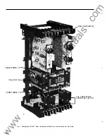
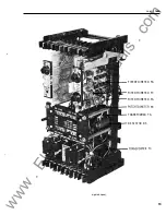
Consists of a zener diode (Zs) mounted on an L
shaped heat sink. The zener is connected to a 2
inch tubular resistor (RS). A small capacitor (C3)
located on the timer module· is connected across
the zener diode.
Telephone Relay
(X)
This is a clapper type auxiliary relay with two
normally open contacts.
Output Relay (AR)
This is a 4 pole normally open high speed aux
iliary output relay used for tripping duty.
The relay coil is connected in series with a 2
inch tubular resistor (RA).
Indicating Contactor Switch
Unit (ICS)
The de indicating contactor switch is a small
clapper type device. A magnetic armature, to
which leaf-spring mounted contacts are attached,
is attracted to the magnetic core upon energization
of the switch. When the switch closes, the moving
contacts bridge two stationary contacts, com
pleting the trip circuit. Also, during this operation,
two fingers on the armature deflect a spring
located on the front of the switch, which allows the
operation indicator target to drop.
The front spring, in addition to holding the
target, provides restraint for the armature and thus
controls the pickup value of the switch.
2
OPERAT I O N
The operation of the SBF- 1 is somewhat
different than the conventional breaker failure
relay. It may be summarized by saying that the
breaker failure relay timer is started by only the
BFI (62X) input rather than the B F I and the over
current fault detector. The breaker failure timer
controls the fault detector so that after it times
out, the overcurrent signal (if present) is connected
to the level detector. This arrangement keeps the
overcurrent input transformer load at a low level.
This permits f�st reset of the secondary voltage of
3 ms or less, even at very high multiples of pickup
current. By use of an additional timer (called the
control timer) the breaker failure timer as well as
the X seal-in relay is reset after it times out. The
circuit operation can be explained by referring to
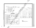
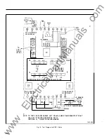
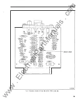
the internal schematic drawing 775B8 1 3 (Fig. 2)
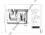
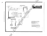
and detailed internal schematic 1 3260 1 9 (Fig. 3).
During stand-by condition the de input to the
relay (terminal 9 positive) is zero since the de con
trol voltage is connected through the breaker
failure initiate contact (see the external schematic)
which is normally open.
Upon the closing of the B F I contact and
providing the de voltage is 80% or greater (of rated
value) a level detector zener diode Z l (connected
to terminal 9) will permit transistor Q2 and Q I to
turn on. The power supply consisting of a 1 0 watt
zener Zs and 25 watt resistor Rs is also energized
which supplies a regulated 24Vdc to the modules
and the X relay. When transistor Q2 and Q l turn
on it connects the regulated power supply to the
control timer which consists of
1/2
of IC I , trim pot
P2 and timing capacitor C l . Resistor R26 and
R27 form a voltage divider which requires ap
proximately one time constant
[(
P2 + R22) x C l )]
before the output terminal 1 2 goes from 24Vdc to
less than 2 .5Vdc. At the same time the control
timer receives power through Q I , the 24 V de out
put of the control timer (term. 1 2 ofiC I ) is used to
turn on transistor Q7 which operates the X relay.
One X contact is brought out to relay terminal 1 5
to permit seal-in of the initiate contact. This is
desirable where the BFI contact is only picked up
for a short time. The initiate contact must be clos
ed for 8 ms in order for seal-in to take place. While
the control timer is timing out, the BF timer will
www
. ElectricalPartManuals
. com


