4-30
JP2/JP3
External signal type
selection
0~20mA / 4~20mA
Analog signal
0~10VDC / 2~10VDC
Analog signal
+
V
AGND
2K
Ω
AI1
AI2
Main Frequency
Reference Command
(voltage or current input)
10
Main Frequency
Reference Command
(voltage or current input)
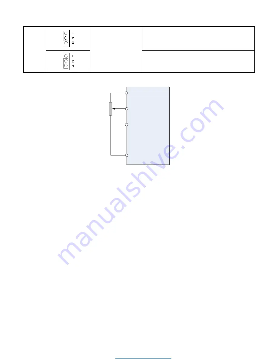
Figure 4.3.4 Analog input as main frequency reference command
00-05/00-06= 4:
Terminal UP / DOWN
The inverter accelerates with the UP command closed and decelerates with the DOWN command closed. Please
refer to parameter 03-00 ~ 03-05 for additional information.
Note:
To use this function both the UP and DOWN command have to be set to any of the input terminals.
00-05/00-06= 5:
Communication Control
The frequency reference command is set via the RS-485 communication port using the MODBUS RTU.
Refer to parameter group 9 for additional information.
00-05/00-06= 6:
PID Output
Enables PID control, reference frequency is controlled by the PID function, refer to chapter 10 or parameter group
10 for PID setup.
00-05/00-06=7
: Pulse Input
Frequency reference from an external pulse input. Can be used only with multi-function input terminal S3 (03-02 =
25 or 26). See parameter group 3 multi-function input selections 25 and 26.
Downloaded from Dealers Industrial Equipment -- Visit


