background image

5

for digital-to-analog converter boxes.
CONSUMER ALERT – This television receiver has only an analog broadcast tuner and will require 
a concerter box after June 12,2009,to receive over-the-air broadcasts with an antenna because of 
the Nation's transition to digital broadcasting. Analog-only TVs should continue to work as before 
with cable and satellite TV services, gaming consoles, VCRs, DVD players, and similar products, For 
more information, call the Federal Communications Commission at 1-888-225-5322(TTY:1-888-
835-5322)or visit the Commission's digital television website at:www.DTV.gov.

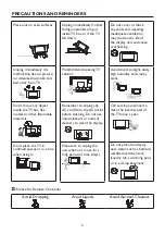
22.   Tilt/Stability – All televisions must comply with recommended international global safety 

standards for tilt and stability properties of its cabinets design.


Do not compromise these design standards by applying excessive pull force to the front, or top, 
of the cabinet, which could ultimately overturn the product


Also, do not endanger yourself, or children, by placing electronic equipment/toys on the top 
of the cabinet. Such items could unsuspectingly fall from the top of the set and cause product 
damage and/or personal injury.

23.   Wall or Ceiling Mounting – The appliance should be mounted to a wall or ceiling only as 

recommended by the manufacturer.

24.   Power Lines – An outdoor antenna should be located away from power lines.
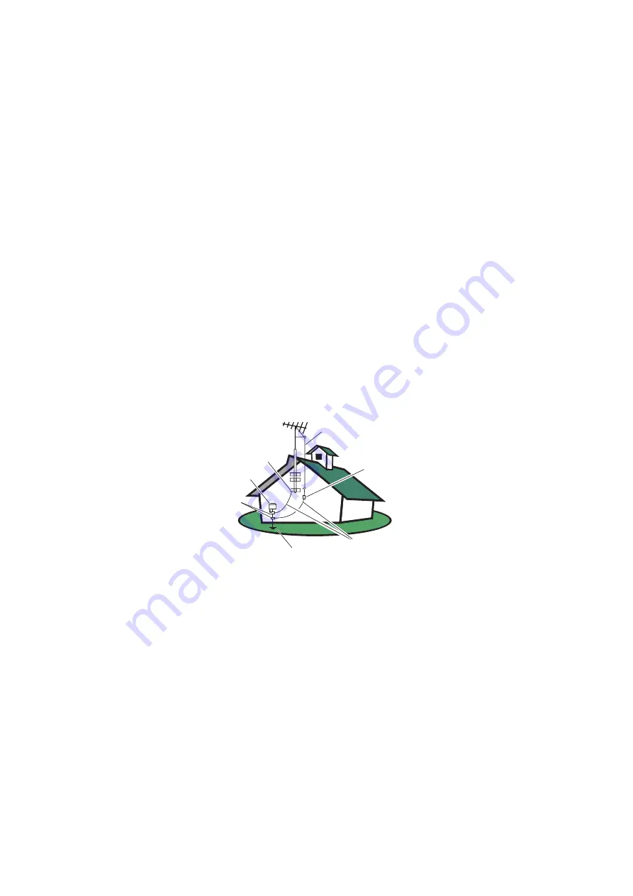
25.   Outdoor Antenna Grounding – If an outside antenna is connected to the receiver, be sure the 

antenna system is grounded so as to provide some protection against voltage surges and built 
up static charges. Section 810 of the National Electric Code, ANSI/NFPA No. 70-1984, provides 
information with respect to proper grounding of the mats and supporting structure grounding of the 
lead-in wire to an antenna-discharge unit, size of grounding connectors, location of antennadischarge 
unit, connection to grounding electrodes and requirements for the grounding electrode. See Figure 
below.

ANTENNA

ANTENNA DISCHARGE UNIT

GROUNDING CONDUCTORS

POWER SERVICE GROUNDING ELECTRODE SYSTEM

GROUND CLAMPS

ELECTRIC SERVICE EQUIPMENT

GROUND CLAMP

EXAMPLE OF ANTENNA GROUNDING AS PER NATIONAL ELECTRICAL CODE Note to the 
CATV system installer: This reminder is provided to call the CATV system installer’s attention to 
Article 820-40 of the NEC that provides guidelines for proper grounding and, in particular, specifies 
that the cable ground shall be connected to the 6 English grounding system of the building, as close 
to the point of cable entry as practical. Please, make sure to connect the power plug to the wall 
outlet socket after connecting the TV to the adapter!

26.   Apparatus shall not be exposed to dripping or splashing and no objects filled with liquids,such as 

vases, shall be placed on the apparatus.

Summary of Contents for TX-42F970Z

Page 1: ...USER S MANUAL MANUEL DE L UTILISATEUR MANUAL DEL USUARIO TX 42F970Z...

Page 2: ...www wde com Westinghouse Digital Electronics Santa Fe Springs CA SE UM 4211 0801...

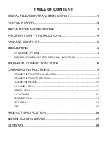
Page 3: ...PARATION 6 ATTACHING THE BASE 6 PREPARINGYOUR LCD HDTV FOR WALL MOUNTING 6 PERIPHERAL CONNECTION GUIDE 8 OPERATING INSTRUCTIONS 9 TO USE THE FRONT PANEL CONTROL 9 TO USE THE REMOTE CONTROL 10 TO USE T...

Page 4: ...onando como antes para otros usos por ejemplo para ver emisoras de TV de baja potencia que todav a transmiten en anal gico para ver pel culas pregrabadas o para utilizar sus videojuegos Para obtener m...

Page 5: ...rticular installation If this equipment does cause harmful interference to radio or television reception which can be determined by turning the equipment off and on the user is encouraged to try to co...

Page 6: ...cleaning Do not use liquid cleaners or aerosol cleaners to clean the display Make sure to unplug the unit when not in use for a long period of time days Do not cover or block any vents and openings I...

Page 7: ...e apparatus has been exposed to rain or moisture does not operate normally or has been dropped 15 The TV should be operated only from the type of power source indicated on the label If you are not sur...

Page 8: ...es An outdoor antenna should be located away from power lines 25 Outdoor Antenna Grounding If an outside antenna is connected to the receiver be sure the antenna system is grounded so as to provide so...

Page 9: ...t least 2 56 inches 65 mm from the wall to prevent cable interference Before mounting your TV on the wall you need to remove the base For your safety please use only with UL listed wall mount bracket...

Page 10: ...EV CH Comp PC HDMI TV Sleep Fav Source EPG Freeze MTS SAP POWER VIDEO COMP PC HDMI TV Power Key Please make sure to connect the power plug to the wall outlet socket after connecting the TV to the powe...

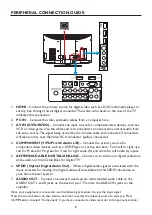
Page 11: ...deo devices such as a DVD Player or set top box here From left to right use red for Pr blue for Pb green forY red for right audio R and white for left audio L inputs 5 ANTENNA CABLE DIGITAL ANALOG Con...

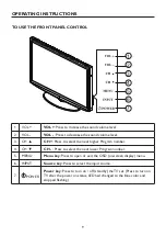
Page 12: ...ess to select the next higher Program number 4 CH CH Press to select the next lower Program number 5 MENU Menu key Press to open or exit the OSD on screen display menu 6 INPUT Source key Press to sele...

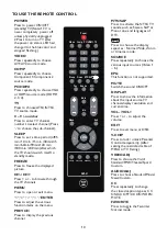
Page 13: ...s function items on the menu PREV CH Press to display the previous channel MTS SAP Press to activate the NTSC TV sounds such as Stereo SAP or Mono tone and languages of DTV Press to choose the display...

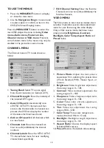
Page 14: ...umbers 6 Channel Labels Show the NTSC ATSC TV channel label menu for user modifying channel labels specifically 7 FAV Channel Setting Show the Favorite Channel List User can edit add delete the favori...

Page 15: ...d off even though the TV speaker is off The default setting is On 9 AVL Choose On or off to adjust volume to be consistent across programs and channels automatically 10 Preset Restore the default audi...

Page 16: ...the parental control function is working The inhibitive channels or source signals can be un lock through pressing theV CHIP key on the remote control and then key in the correct password Note This fe...

Page 17: ...Automatic Solid Flashing Transparent Translucent Edge Effect Automatic None Raised Depressed Uniform Left Shadow Right Shadow Edge Color Automatic Red Green Blue Yellow Magenta Cyan Black White 11 Inp...

Page 18: ...designed to provide reasonable protection against harmful interference in a residential installation This equipment generates uses and can radiate radio frequency energy and if not installed and used...

Page 19: ...S VIDEO INPUT Y 1V p p 75 ohm negative sync C 0 286V p p burst signal 75 ohm VIDEO AUDIO INPUT VIDEO 1V p p 75 ohm negative sync AUDIO 300mv rms Component INPUT Rear Component x2 Y 1V p p 75 ohm inclu...

Page 20: ...her channel Adjust the contrast and brightness settings Check the Closed Captions control Some TEXT modes could block the screen Good picture but no sound Increase theVOLUME Check if the TV is muted p...

Page 21: ...TV HDTV displays are technically defined as being capable of displaying a minimum of 720p or 1080i active scan lines HDMI Inputs High Definition Multimedia Interface Audio Video Inputs Located on the...

Page 22: ...19...

Reviews: