31
WHL-016 REV. 12.18.14
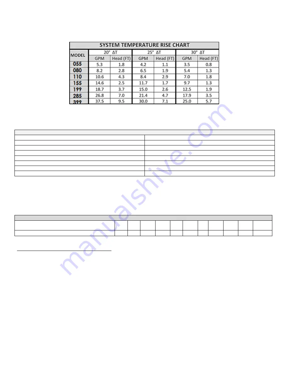
The chart below represents the various system design temperature rise through the boiler along with their respective flows and friction
loss, which will aid in circulator selection.
In addition, the boiler heat exchanger has a minimum total water volume that must be taken into account when sizing the circulator.
Minimum boiler flow rates are listed in the table below.
MINIMUM BOILER FLOW RATES
MODEL
MINIMUM FLOW RATE (GPM)
055
3.5
080
5.4
110
7
155
9.7
199
12.5
285
17.9
399
25
Table 6
– Minimum Boiler Flow Rates
The chart below represents the combined flow rates and pipe sizes when using multiple boilers to design the manifold system for the
primary circuit. To size, simply add up the number of boilers and the required flow rates for the system design temperature.
Example: (5) 055 boilers with a design of 20°
Δt degree temperature rise with each boiler having an individual flow rate of 5.3 GPM. To
correctly size the manifold feeding these (5) boilers you would need a pipe size of 2
”.
MULTIPLE BOILER MANIFOLD PIPING
Maximum Flow Rate
(GPM at 3 feet per second)
8
14
19
31.5
45
69
93
120
150
188
271
Schedule 40 Pipe Diameter (Inches)
1
1¼
1½
2
2½
3
3½
4
4½
5
6
Table 7
J. CHECK/CONTROL WATER CHEMISTRY
NOTE:
BOILER FAILURE DUE TO IMPROPER WATER CHEMISTRY IS NOT COVERED BY WARRANTY.
Sodium less than 20 mGL
Water pH between 6 and 8
1. Maintain boiler water pH between 6 and 8. Check with litmus paper or have chemically analyzed by water treatment company.
2. If pH differs from above, consult local water treatment company for treatment needed.
Hardness less than 7 grains
Consult local water treatment companies for unusually hard water areas (above 7 grains hardness).
Chlorine concentration less than 100 ppm
1. Filling with chlorinated fresh water should be acceptable since drinking water chlorine levels are typically less than 5 ppm.
2. Do not use the boiler to directly heat swimming pool or spa water.
3. Do not fill boiler or operate with water containing chlorine in excess of 100 ppm.
Table 5
– Boiler Flow Rates
Summary of Contents for WBCNG399W
Page 14: ...14 WHL 016 REV 12 18 14 SPECIFICATIONS AND DIMENSIONS Figure 2 Specifications and Dimensions ...
Page 24: ...24 WHL 016 REV 12 18 14 Figure 8 Piping Symbol Legend ...
Page 59: ...59 WHL 016 REV 12 18 14 Figure 32 Cascade Master and Follower Wiring ...
Page 60: ...60 WHL 016 REV 12 18 14 Figure 33 Internal Connection Diagram LP 293 J ...
Page 83: ...83 WHL 016 REV 12 18 14 055 080 110 PARTS BREAKDOWN Figure 36 Replacement Parts LP 387 J ...
Page 85: ...85 WHL 016 REV 12 18 14 155 199 285 399 PARTS BREAKDOWN ...
Page 86: ...86 WHL 016 REV 12 18 14 Figure 38 Replacement Parts LP 387 KK ...
Page 87: ...87 WHL 016 REV 12 18 14 155 199 285 399 MODEL PARTS BREAKDOWN ...
Page 91: ...91 WHL 016 REV 12 18 14 ...
Page 92: ...92 WHL 016 REV 12 18 14 ...


