78
WHL-016 REV. 12.18.14
SCREEN
DESCRIPTION
POSSIBLE REMEDY
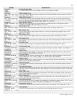
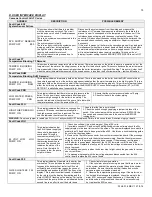
Fault Code F20
CONDENSATE FULL F20
PUMP ON
The condensate trap is full. The red light will
display and the word LOCKOUT will flash. This
code indicates a serious safety issue. The boiler
will not restart until the cause is determined by a
technician and he pushes the RESET button on
the display. During this lockout fault, the pump
will be off as indicated on the second line of the
display.
1. Check condensate lines for obstructions.
2. Check wiring from condensate reservoir to 926 control. Verify the
leads are green and red. Repair as necessary.
Fault Code F31
PROGRAM ERROR
F31
There was an error while programming the con-
trol and the memory is corrupt. The boiler control
will not function in this state and the pump will be
off as indicated on the bottom line. This error
only occurs if a technician is programming the
control and the programming function fails. The
only way to recover from this error is to repro-
gram the control. If this error occurs at any time
other than when a technician is servicing the
boiler, the control has failed and must be
replaced by a qualified technician
The control must be re-programmed. If programming does not solve
problem, the control must be replaced.
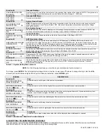
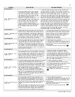
Fault Code PP
CONTROL PROGRAMED
PP
The control has been programmed by a
technician or the factory. After programming, the
control is left in a locked out mode. Press the
RESET key for at least 1 second to begin use of
the control.
Fault Code FOU
OUTDOOR SENSOR FOU
PUMP ON 1:45P
There is an issue with the outdoor sensor. It is
shorted, damaged, or disconnected from the
boiler.
1. Check outdoor sensor connections and wiring. Ensure the sensor
and wiring are intact and that the sensor is connected to the boiler.
2. Check the outdoor sensor resistance with an ohmmeter. See
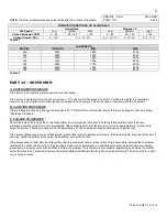
Table 30 for correct outdoor sensor resistance.
3. Replace the outdoor sensor.
NOTE:
If an outdoor sensor IS NOT used in the installation, enter the System Setting Program Navigation, go to Function 21, and turn the setting from
ON to OFF.
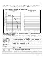
The following blocking codes will block operation until the control determines the situation safe for boiler operation.
Blocking Code E07
FLUE TEMP HIGH E07
PUMP OFF TIME
This display indicates that the flue sensor tem-
perature is excessive and above 210
o
F. When
this code is displayed, the boiler will not respond
to a demand for heat. When the flue temperature
decreases below 194
o
F, the display will return to
normal and allow the boiler to respond to a heat
demand. The bottom line indicates the status of
the pump. The pump will remain off when this
error is displayed.
Check the flue for obstructions or any sign of damage, especially
signs of excessive heat. Repair as necessary. Run the boiler and
check the flue temperature with an external thermometer. If the flue
temperature on the thermometer does not agree with the flue
temperature displayed in the status menu, inspect the wiring to the
flue temperature sensor in the boiler and repair as necessary. If the
wiring is intact, replace the flue sensor. If the flue temperature is
excessive on the status menu and the test thermometer reads the
same, check and adjust combustion controls on the boiler. If the
problem persists, inspect the target wall in the combustion chamber
and replace it if cracked or damaged.
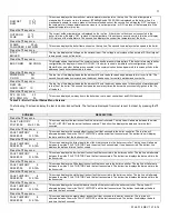
Blocking Code E19
LINE VOLTAGE
PUMP OFF E19
This display indicates that the line voltage fre-
quency is out of range. This could happen if the
boiler is being powered from a small gasoline
powered generator that is not functioning cor-
rectly or overloaded.
Inspect power wiring to boiler and repair as necessary. If connected
to line voltage, notify the power company. If connected to an
alternate power source such as generator or inverter, make sure the
line voltage frequency supplied by the device is 60 Hz.
Table 29
– Fault and Blocking Code Screens
Summary of Contents for WBCNG399W
Page 14: ...14 WHL 016 REV 12 18 14 SPECIFICATIONS AND DIMENSIONS Figure 2 Specifications and Dimensions ...
Page 24: ...24 WHL 016 REV 12 18 14 Figure 8 Piping Symbol Legend ...
Page 59: ...59 WHL 016 REV 12 18 14 Figure 32 Cascade Master and Follower Wiring ...
Page 60: ...60 WHL 016 REV 12 18 14 Figure 33 Internal Connection Diagram LP 293 J ...
Page 83: ...83 WHL 016 REV 12 18 14 055 080 110 PARTS BREAKDOWN Figure 36 Replacement Parts LP 387 J ...
Page 85: ...85 WHL 016 REV 12 18 14 155 199 285 399 PARTS BREAKDOWN ...
Page 86: ...86 WHL 016 REV 12 18 14 Figure 38 Replacement Parts LP 387 KK ...
Page 87: ...87 WHL 016 REV 12 18 14 155 199 285 399 MODEL PARTS BREAKDOWN ...
Page 91: ...91 WHL 016 REV 12 18 14 ...
Page 92: ...92 WHL 016 REV 12 18 14 ...


