81
WHL-016 REV. 12.18.14
2. Close isolation valves on the return and supply connections to the boilers as shown in the piping diagrams within this manual. Slowly
open the ball valves and release pressure into a bucket. Once pressure is released, connect a hose to the water line to flush the boiler.
Scale removing solution may be used, but must be approved for use with stainless steel and FDA approved for use in a potable water
system.
3. Thoroughly flush the heat exchanger before commissioning the boiler back in service.
D. MAINTAINING THE CONDENSATE SYSTEM
The condensate trap assembly MUST BE PROPERLY INSTALLED according to these instructions when operating the boiler.
Operating the boiler without the condensate trap assembly will cause flue gases to leak and result in serious personal injury or death.
When servicing is complete, make sure the condensate collector cap is replaced securely. Failure to do so will cause venting issues
that will result in serious injury or death.
1. Ensure the boiler is powered off.
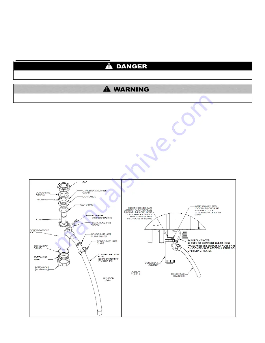
2. Remove the stainless steel lock pin to release the condensate trap. Remove the clear plastic hose from the hose barb. Remove the
trap from the drain tube.
3. Remove the bottom cap from the condensate trap.
4. Flush trap with fresh water to remove debris from the trap.
NOTE:
Ensure the float moves freely within the trap. If the float does not move, DO NOT reinstall the trap.
5. When the condensate trap is sufficiently clean, reinstall the bottom cap on the trap.
NOTE:
Ensure all parts shown in Figure 35-1, Condensate Detail, are installed with the condensate trap. If any parts are missing, DO
NOT reinstall the trap. Replace the entire assembly.
Figure 35-1 - Condensate Detail, 35-2
– Condensate Trap Installation
Summary of Contents for WBCNG399W
Page 14: ...14 WHL 016 REV 12 18 14 SPECIFICATIONS AND DIMENSIONS Figure 2 Specifications and Dimensions ...
Page 24: ...24 WHL 016 REV 12 18 14 Figure 8 Piping Symbol Legend ...
Page 59: ...59 WHL 016 REV 12 18 14 Figure 32 Cascade Master and Follower Wiring ...
Page 60: ...60 WHL 016 REV 12 18 14 Figure 33 Internal Connection Diagram LP 293 J ...
Page 83: ...83 WHL 016 REV 12 18 14 055 080 110 PARTS BREAKDOWN Figure 36 Replacement Parts LP 387 J ...
Page 85: ...85 WHL 016 REV 12 18 14 155 199 285 399 PARTS BREAKDOWN ...
Page 86: ...86 WHL 016 REV 12 18 14 Figure 38 Replacement Parts LP 387 KK ...
Page 87: ...87 WHL 016 REV 12 18 14 155 199 285 399 MODEL PARTS BREAKDOWN ...
Page 91: ...91 WHL 016 REV 12 18 14 ...
Page 92: ...92 WHL 016 REV 12 18 14 ...


