17
WHL-016 REV. 12.18.14
NOTE: DAMAGE TO THE BOILER CAUSED BY EXPOSURE TO
CORROSIVE VAPORS IS NOT COVERED BY WARRANTY.
(Refer to the
limited warranty for complete terms and conditions).
G. REMOVING AN BOILER FROM A COMMON VENT SYSTEM
Do not install the boiler into a common vent with any other boiler. This will
cause flue gas spillage or boiler malfunction, resulting in possible
substantial property damage, severe personal injury, or death.
Failure to follow all instructions can result in flue gas spillage and carbon
monoxide emissions, causing severe personal injury or death.
When removing an existing boiler, the following steps must be followed.
1. Seal any unused openings in the common venting system.
2. Visually inspect the venting system for proper size and horizontal pitch to
determine if there is blockage, leakage, corrosion or other deficiencies that
could cause an unsafe condition.
3. If practical, close all building doors, windows and all doors between the common venting system and other spaces in the building.
Turn on clothes dryers and any boilers not connected to the common venting system. Turn on any exhaust fans, such as range hoods
and bathroom exhausts, at maximum speed. Do not operate a summer exhaust fan. Close all fireplace dampers.
4. Place in operation the boiler being inspected. Follow the lighting instructions. Adjust the thermostat so the boiler will operate
continuously.
5. Test for spillage at the draft hood relief opening after 5 minutes of main burner operation. Use the flame of a match or candle or
smoke from a cigarette.
6. After it has been determined that each boiler remaining connected to common venting system properly vents when tested as
outlined, return doors, windows, exhaust fans, fireplace dampers and any other gas burning boiler to their previous condition of use.
7. Any improper operation of the common venting system should be corrected so the installation conforms to the National Fuel Gas
Code, ANSI Z223.1. When resizing any portion of the common venting system, the common venting system should be resized to
approach the minimum size as determined using the appropriate tables in Appendix G in the National Fuel Gas Code, ANSI Z 223.1.
PART 4 – PREPARE BOILER
UNCRATING BOILER
– Any claims for damage or shortage in shipment must be filed immediately against the transportation company
by the consignee.
Cold weather handling
– If boiler has been stored in a very cold location (below 0
o
F) before installation, handle with care until the plastic
components come to room temperature.
A. REMOVE THE BOILER FROM PACKAGING
Remove all sides of the shipping crate, and the wooden block that holds the boiler in place during shipping. Slide the boiler from the
mounting bracket, which is affixed to the skid (Figure 4 and 5). Remove the mounting bracket from the crate (Figure 5). Take care to
place the boiler in a safe location prior to installation to prevent damage to the mechanical connections.
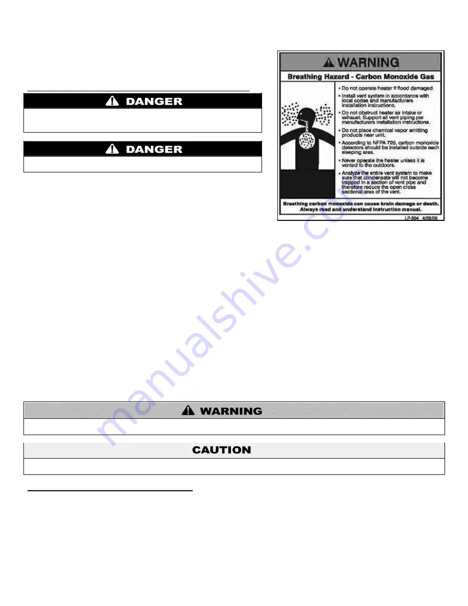
Figure 3
– CO Warning Label
Summary of Contents for WBCNG399W
Page 14: ...14 WHL 016 REV 12 18 14 SPECIFICATIONS AND DIMENSIONS Figure 2 Specifications and Dimensions ...
Page 24: ...24 WHL 016 REV 12 18 14 Figure 8 Piping Symbol Legend ...
Page 59: ...59 WHL 016 REV 12 18 14 Figure 32 Cascade Master and Follower Wiring ...
Page 60: ...60 WHL 016 REV 12 18 14 Figure 33 Internal Connection Diagram LP 293 J ...
Page 83: ...83 WHL 016 REV 12 18 14 055 080 110 PARTS BREAKDOWN Figure 36 Replacement Parts LP 387 J ...
Page 85: ...85 WHL 016 REV 12 18 14 155 199 285 399 PARTS BREAKDOWN ...
Page 86: ...86 WHL 016 REV 12 18 14 Figure 38 Replacement Parts LP 387 KK ...
Page 87: ...87 WHL 016 REV 12 18 14 155 199 285 399 MODEL PARTS BREAKDOWN ...
Page 91: ...91 WHL 016 REV 12 18 14 ...
Page 92: ...92 WHL 016 REV 12 18 14 ...


