19
WHL-016 REV. 12.18.14
b. The provided mounting bracket must be mounted directly to the center of at least 2 studs using standard steel or stainless steel
¼” x
2 ½
” lag bolts for all models. Be sure the bracket is level and mark the hole location of the bracket height and horizontal stud location.
Ensure the marked holes are located in the center of the building frame (studs).
c. For all models,
2 ½” is the minimum lag bolt length if the bracket is directly on stud. Increase lag bolt length for any materials
covering the studs.
d. Predrill pilot holes on the marked stud locations. The pilot holes for bare studs should be
2” deep for all models. See table below for
pilot hole diameter by wood type. Increase length for any material covering the stud. Ensure that the predrilled holes are straight and
square to the wall. Failure to do so could lead to insufficient support or out of level boiler. See Figure 6.
NOTE:
Bolt must embed into the wood structure a minimum of 2”.
d. Using the predrilled holes, mount the hanger bracket to the building frame (studs) using the appropriately sized standard steel (or
stainless) lag bolt. Hang boiler on the wall mounted bracket. Be sure that the bracket is engaged before letting the boiler hang free.
Slowly release the weight of the boiler while ensuring that the bracket is properly secured. Verify that the boiler is securely mounted
before leaving the boiler unsupervised.
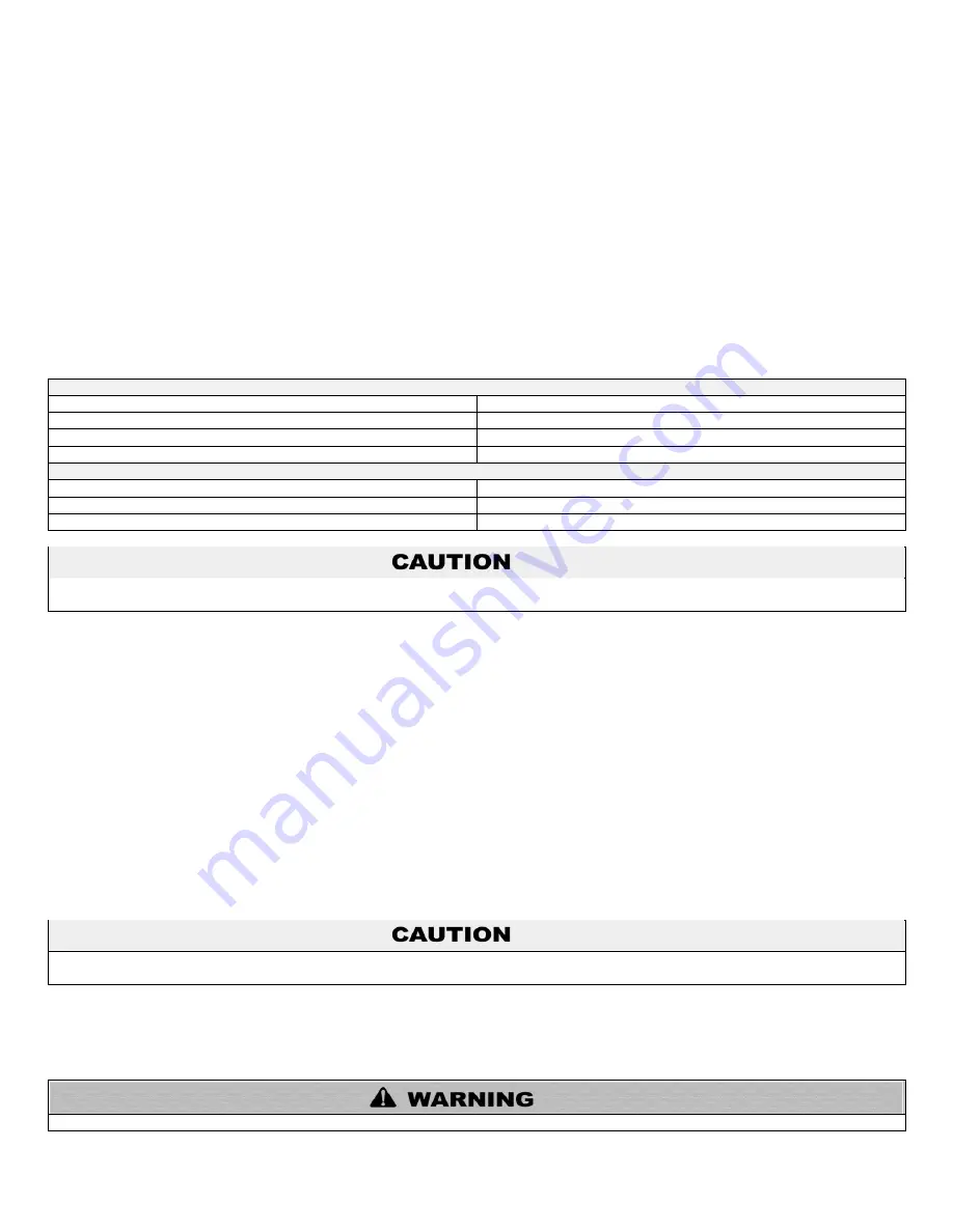
REQUIRED AMOUNT OF BOLTS FOR WALL MOUNTING THE BOILER
MODEL
AMOUNT OF BOLTS
055
–110
2
155
– 285
4
399
6
PILOT HOLE SIZE BY WOOD TYPE
TYPE
DRILL BIT SIZE
SOFT
3/32
”
HARD
3/16”
If the boiler is not installed vertically plumb, improper and unsatisfactory operation may occur, causing excessive condensation build-up,
nuisance fault codes, and unnecessary maintenance.
2. MOUNTING TO A METAL FRAME
a. The provided mounting bracket must be mounted to the center of at least 2 studs using standard steel or stainless steel toggle bolts
3/16” diameter or larger, and at least 2” long for direct mounting on stud for 055 – 110 models, and 3/8” diameter or larger, and at least
2” long for 155 – 399 models for direct mounting on at least 18 gauge studs. Be sure the bracket is level and mark the hole location of
the top bracket height and horizontal stud location. Ensure the marked holes are located in the center of the building frame (studs).
b. 2” is the minimum toggle bolt length if the bracket is directly on stud. Increase length for any materials covering the studs.
c. Predrill holes on the marked stud locations. The predrilled holes should be ½” in diameter for 3/16” bolts, and ¾” in diameter for 3/8”
bolts, to allow for the collapsed wings of the toggle to slide through. Ensure that the predrilled holes are straight and square to the wall.
Failure to do so could lead to insufficient support of out of level boiler. See Figure 6.
d. Using the predrilled holes, mount the hanger bracket to the building frame (studs) with the toggle bolts. Ensure that the bolt toggles
are through the stud and expanded catching the inside of the stud. Tighten the toggle bolt until the mounting bracket is secure. Hang
boiler on the now wall mounted bracket. Be certain that the bracket is engaged before letting the boiler hang free. Slowly release the
weight of the boiler while ensuring the bracket is properly secure. Verify that the boiler is securely mounted before leaving it
unsupervised.
If the boiler is not installed upright and level, improper and unsatisfactory operation may occur, causing excessive condensation build-
up, nuisance fault codes, and unnecessary maintenance.
PART 5 – BOILER PIPING
Failure to follow the instructions in this section WILL VOID the warranty and may result in property damage, serious injury, or death.
Summary of Contents for WBCNG399W
Page 14: ...14 WHL 016 REV 12 18 14 SPECIFICATIONS AND DIMENSIONS Figure 2 Specifications and Dimensions ...
Page 24: ...24 WHL 016 REV 12 18 14 Figure 8 Piping Symbol Legend ...
Page 59: ...59 WHL 016 REV 12 18 14 Figure 32 Cascade Master and Follower Wiring ...
Page 60: ...60 WHL 016 REV 12 18 14 Figure 33 Internal Connection Diagram LP 293 J ...
Page 83: ...83 WHL 016 REV 12 18 14 055 080 110 PARTS BREAKDOWN Figure 36 Replacement Parts LP 387 J ...
Page 85: ...85 WHL 016 REV 12 18 14 155 199 285 399 PARTS BREAKDOWN ...
Page 86: ...86 WHL 016 REV 12 18 14 Figure 38 Replacement Parts LP 387 KK ...
Page 87: ...87 WHL 016 REV 12 18 14 155 199 285 399 MODEL PARTS BREAKDOWN ...
Page 91: ...91 WHL 016 REV 12 18 14 ...
Page 92: ...92 WHL 016 REV 12 18 14 ...


