background image

16 | Westinghouse Outdoor Power Equipment, LLC


OPERATION

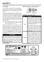
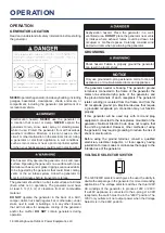
GENERATOR LOCATION

Read and understand all safety information before starting 

the generator. 

NEVER

 operate the generator inside any building, including 

garages, basements, crawlspaces, sheds, enclosure, or 

compartment, including the generator compartment of a 

recreational vehicle.  

Electrocution hazard. 

NEVER

 use the generator in 

a location that is wet or damp. 

NEVER

 expose the 

generator to rain, snow, water spray, or standing water 

while in use. Protect the generator from all hazardous 

weather conditions. Moisture or ice can cause a short 

circuit or other malfunction in the electrical circuit. Using 

a generator or electrical appliance in wet conditions, 

such as rain or snow, or near a pool or sprinkler system, 

or when your hands are wet, could result in electrocution

Fire hazard. Only operate the generator on a solid, level 

surface. Operating the generator on a surface with loose 

material such as sand or grass clippings can cause debris 

to be ingested by the generator that could block cooling 

vents or the air intake system. Allow the generator to 

cool for 30 minutes before transport or storage.

The generator should be on a flat, level surface at all times 

(Even while not in operation). The generator must have 

at least 5 ft. (1.5 m) of clearance from all combustible 

material. 

DO NOT

 operate the generator in the back of a SUV, 

camper, trailer, truck bed (regular, flat, or otherwise), under 

stairs, next to walls or buildings, or in any other location 

that will not allow for adequate cooling of the generator 

and/or  the  muffler. 

DO NOT

 contain generators during 

operation.

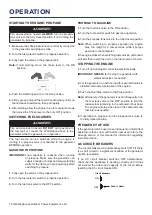
Asphyxiation hazard. Place the generator in a well-

ventilated area. 

DO NOT

 place the generator near vents 

or intakes where exhaust fumes could be drawn into 

occupied  or  confined  spaces.  Carefully  consider  wind 

and air currents when positioning the generator.

GROUNDING

Shock hazard. Failure to properly ground the generator 

can result in electric shock.

NOTICE

Only use grounded 3-prong extension cords, tools, and 

appliances, or double-insulated tools and appliances.

The  generator  neutral  is  floating.  The  generator  ground 

t

erminal is connected to the frame of the generator, the 

metal non-current-carrying parts of the generator, and 

the ground terminals of each receptacle. The generator 

(stator winding) is isolated from the frame and from the 

AC receptacle ground pin. Electrical devices that require 

a grounded receptacle pin connection may not function 

properly. 
If this generator will be used only with cord and plug 

equipment connected to the receptacles mounted on the 

generator, National Electric Code does not require that 

the unit be grounded. However, other methods of using 

the generator may require grounding to reduce the risk of 

shock or electrocution. 

Before  using  the  ground  terminal,  consult  a  qualified 

electrician, electrical inspector, or local agency having 

jurisdiction for local codes or ordinances that apply to the 

intended use of the generator. 

VOLTAGE SELECTOR SWITCH

The 120V/240V selector switch gives the user the ability to 

double the amperage in the generator for more demanding 

applications. The voltage selector switches the dual 120V 

AC windings of the generator to produce 120V or 240V. 

If a 240V appliance is connected to the 4-prong L14-30R 

receptacle, the switch must be in the “240V” position. The 

120V only outlets will not output power when the Voltage 

Selector is in the 240V position.

OPERATION 

Summary of Contents for WGEN5300DFC

Page 1: ...ODUCT TO THE STORE If you have questions or need assistance please call customer service at 855 944 3571 WGen5300DFc Dual Fuel Portable Generator Gasoline 5300 Running Watts 6600 Peak Watts Propane 48...

Page 2: ...CONTENTS DISCLAIMERS 2 ALL RIGHTS RESERVED 2 INTRODUCTION SPECIFICATIONS 3 SAFETY SAFETY DEFINITIONS 4 SAFETY SYMBOLS 4 SAFETY INSTRUCTIONS 5 SAFETY LABELS 8 SAFETY LABELS 9 CO SENSOR 10 ACTION LABEL...

Page 3: ...ntinuous operation at ambient temperatures up to 104 F 40 C If needed this product can be operated at temperatures ranging from 5 F 15 C 122 F 50 C for short periods If the product is exposed to tempe...

Page 4: ...esult in death or serious injury Indicates a hazardous situation which if not avoided could result in minor or moderate injury NOTICE Indicates a situation which can cause damage to the generator pers...

Page 5: ...properly installed and the electrical output has been verified by a qualified electrician The connection must isolate the generator power from utility power and must comply with all applicable laws a...

Page 6: ...A transfer switch must be installed by a licensed electrician approved by the authority having jurisdiction The installation must comply with all applicable laws and electrical codes FUEL SAFETY Stor...

Page 7: ...not used the regulator that is attached to the fuel tank The pressure as measured at the regulator mounted to the generator must be 7 to 14 of water column A certified plumber must ensure that the pr...

Page 8: ...8 Westinghouse Outdoor Power Equipment LLC SAFETY LABELS SAFETY...

Page 9: ...Westinghouse Outdoor Power Equipment LLC 9 SAFETY SAFETY LABELS...

Page 10: ...attery powered carbon monoxide alarm s in your home WARNING Automatic shutoff accompanied with a flashing RED light in the CO Sensor portion of the control panel is an indication that the generator wa...

Page 11: ...5 20R Receptacles Receptacles can supply a maximum of 20 Amps 9 20 Amp AC Circuit Breaker Circuit breaker limits the current that can be delivered through the NEMA 5 20R receptacles to 20 Amps 10 30...

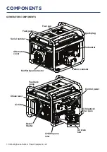
Page 12: ...NERATOR COMPONENTS Oil drain bolt Oil dipstick filler neck Fuel cap Fuel gauge Muffler spark arrestor Carbon canister Carburetor Alternator cover Control panel Recoil Starter Air filter Fuel tank valv...

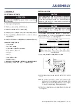
Page 13: ...OTICE THIS GENERATOR HAS BEEN SHIPPED WITHOUT OIL DO NOT attempt to crank or start engine before it has been properly serviced with recommended oil Failure to add engine oil before starting will resul...

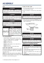
Page 14: ...e fuel system Follow the manufacturer s instructions for use ALWAYS mix the correct amount of fuel stabilizer to gasoline in an approved gasoline container before fueling the generator Run the generat...

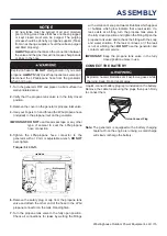
Page 15: ...ane hose connector to the generator with a 19 mm or adjustable wrench DO NOT over tighten Torque 5 10 lb ft 6 Remove the safety plug or cap from the propane tank valve and attach the other end of the...

Page 16: ...yxiation hazard Place the generator in a well ventilated area DO NOT place the generator near vents or intakes where exhaust fumes could be drawn into occupied or confined spaces Carefully consider wi...

Page 17: ...fuel choice Turn the fuel selector switch fully upward for gasoline operation Turn the fuel selector switch fully downward for propane operation BREAK IN PERIOD For proper break in DO NOT exceed 50 o...

Page 18: ...to the ON position 2 Turn the fuel selector switch to gasoline operation 3 Turn the propane tank valve to the fully closed position Note When switching to propane operation the engine may run rough fo...

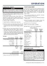
Page 19: ...Total Starting Watts Needed 4190 Wattages listed are approximate Verify actual wattage POWER MANAGEMENT To prolong the life of the generator and attached devices use care when adding electrical loads...

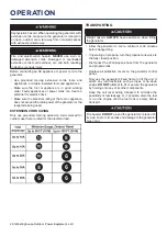
Page 20: ...the receptacle being used EXTENSION CORD SIZING Only use grounded 3 prong extension cords marked for outdoor use that are rated for the electrical load TRANSPORTING Weight hazard ALWAYS have assistan...

Page 21: ...ons Replace air filter if it cannot be adequately cleaned 3 Recommend service to be performed by authorized Westinghouse service dealer MAINTENANCE REMINDERS Maintenance reminder codes will be shown o...

Page 22: ...ag clean around the oil dipstick 3 Remove the oil dipstick and wipe the dipstick clean 4 Insert the dipstick into the oil filler neck without screwing it in Remove the dipstick and verify that the oil...

Page 23: ...spark plug Replace if electrodes are pitted burned or the insulator is cracked Only use a recommended replacement plug 6 Measure the spark plug electrode gap with a wire type feeler gauge If necessar...

Page 24: ...The use of fuel stabilizer significantly increases the storage life of gasoline Full time use of fuel stabilizer is recommended Follow the manufacturer s instructions for use STORAGE TIME RECOMMENDED...

Page 25: ...osition will help prevent internal corrosion Return the recoil handle gently 8 Reinstall the spark plug Leave the spark plug boot disconnected to prevent accidental starting VALVE CLEARANCE NOTICE Che...

Page 26: ...lter Bad fuel generator stored without treating or draining gasoline or refueled with bad gasoline Drain the fuel tank Refuel with fresh gasoline Fuel system malfunction fuel pump failure ignition mal...

Page 27: ...rmal immediately discontinue use and have the propane regulator inspected by a qualified technician Residual fuel from the carburetor dispersing after operation Normal no correction is needed Poor per...

Page 28: ...28 Westinghouse Outdoor Power Equipment LLC EXPLODED VIEWS EXPLODED VIEWS AND PARTS LIST ENGINE EXPLODED VIEW...

Page 29: ...ASKET 9 3 401102 CYLINDER HEAD INTERNAL COVER NO PART DESCRIPTION 9 4 96226 INTERNAL COVER GASKET 9 5 401101 CYLINDER HEAD COVER 9 6 92036 SCREW 9 7 95603 BREATHER TUBE 9 8 94435 BREATHER TUBE CLIP 10...

Page 30: ...3 404601 IMPELLER 15 4 90003 NUT 16 50090067 RECOIL STARTER ASSEMBLY 16 1 91325 BOLT 16 2 404707 221A RECOIL STARTER ASSEMBLY 16 2 1 5943 RECOIL HANDLE 16 2 2 5942 221 RECOIL COVER 16 3 260801 Q SHAP...

Page 31: ...Westinghouse Outdoor Power Equipment LLC 31 EXPLODED VIEWS GENERATOR EXPLODED VIEW...

Page 32: ...FILTER CONNECTING PIPE 6 2 91327 BOLT M6 6 3 94402 FUEL LINE CLAMP 6 4 94408 FUEL LINE CLAMP NO PART DESCRIPTION 6 5 543601L CARBON CANISTER ASSEMBLY 6 6 95020 CARBON CANISTER AND FUEL TANK CONNECTING...

Page 33: ...2 221 ALTERNATOR TAIL COVER 10 9 91323 BOLT M5 10 10 91513 BOLT M5 10 11 90009 NUT M5 10 12 532303 052 TAIL BRACKET FIXING PLATE 10 13 94204 SPRING WASHER 11 CO MODULE ASSEMBLY 11 1 599064 CO MODULE 1...

Page 34: ...34 Westinghouse Outdoor Power Equipment LLC SCHEMATICS SCHEMATICS SCHEMATICS...

Reviews: