Westinghouse Portable Power | 27
6. If an adjustment is required, hold the adjusting nut and
loosen the jam nut.
7.
Turn the adjusting nut to obtain the correct valve lash.
When the valve lash is correct, hold the adjusting nut
and tighten the jam nut to 106 in-lb (12 N•m).
8. Recheck the valve lash after tightening the jam nut.
9.
Perform this procedure for both the intake and
exhaust valves.
10.
Install the rocker arm cover, gasket and spark plug.
TESTING GFCI OUTLETS
1. Start the generator and allow it to warm up.
2.
Press the test button on the GFCI outlet.
Test Button
Reset Button
3. The reset button should pop out and there will be
no power from the outlets. If the reset button does
not pop out, the GFCI outlet is not working correctly
and must be repaired before the generator can be
operated.
4. Press the reset button to restore power to the outlet.
BATTERY SERVICE
WARNING
Do not charge for over 8 hours. Leaving the
charger plugged in indefinitely could overcharge
the battery and lead to battery failure.
To ensure the battery remains charged, the generator
should be started every 2 to 3 months and run for a
minimum of 15 minutes or a charger should be plugged
into the generator and the generator should be charged
overnight. Make sure the engine control switch is in the
STOP
position when charging. Plug the cord from the
charger into the charging port on the generator control
panel. Plug the charger into a 110/120-volt AC outlet.
CHECKING AND ADJUSTING VALVE LASH
CAUTION
Checking and adjusting valve lash
must be done when the engine is cold.
1.
Remove the rocker arm cover and carefully remove
the gasket. If the gasket is torn or damaged, it must
be replaced.
2.
Remove the spark plug so the engine can be rotated
more easily.
3.
Rotate the engine to top dead center (TDC) of the
compression stroke. Looking through the spark plug
hole, the piston should be at the top.
4.
Both the rocker arms should be loose at TDC on the
compression stroke. If they are not, rotate the engine
360°.
5.
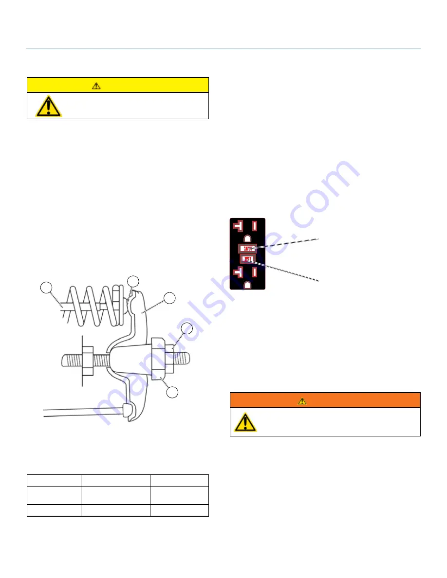
Insert a feeler gauge between the rocker arm and the
push rod and check for clearance (see Figure 24). See
Table 3 for valve lash specifications.
1
2
3
4
5
Figure 24
(1) Push Rod, (2) Feeler Gauge Area
(3) Rocker Arm, (4) Jam Nut, (5) Adjusting Nut
(Table 3) Standard Valve Lash
Intake Valve
Exhaust Valve
Valve Lash
0.0035 ± 0.0043 in
(0.09 ± 0.11 mm)
0.0043 ± 0.0051 in
(0.11 ± 0.13 mm)
Bolt Torque
8-12N.m
8-12N.m
MAINTENANCE
Summary of Contents for WGen7500
Page 1: ...USER MANUAL WGen7500 Portable Generator 7500 Running Watts 9500 Peak Watts REMOTE START...
Page 8: ...8 Westinghouse Portable Power SAFETY SAFETY LABELS AND DECALS 8 9 7 10 8 9 6 6 7 5 10...
Page 31: ...Westinghouse Portable Power 31 WGen7500 SCHEMATIC...
Page 32: ...32 Westinghouse Portable Power WGen7500 EXPLODED VIEW...
Page 37: ...Westinghouse Portable Power 37 Version 07 31 18KD...


