background image

2 | Westinghouse Portable Power

DISCLAIMERS:

All information, illustrations and specifications in this manual are based on the latest information available at

the time of publishing. The illustrations used in this manual are intended as representative reference views only.

Moreover, because of our continuous product improvement policy, we may modify information, illustrations and/or

specifications to explain and/or exemplify a product, service or maintenance improvement. We reserve the right

to make any change at any time without notice. Some images may vary depending upon which model is shown.

ALL RIGHTS RESERVED:

No part of this publication may be reproduced or used in any form by any means – graphic, electronic or

mechanical, including photocopying, recording, taping or information storage and retrieval systems – without the

written permission of MWE Investments LLC.

DANGER

This manual contains important instructions for operating this generator. For your safety

and the safety of others, be sure to read this manual thoroughly before operating the

generator. Failure to properly follow all instructions and precautions can cause you and

others to be seriously hurt or killed.

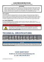
Model 

Number

Running 

Watts 

Peak 

Watts 

Fuel 

Tank 

Size 

(L/G)

Rated 

Speed 

(RPM)

Ignition 

Type

Spark 

plug

Engine 

Disp (cc)

Stroke X 

Bore

Oil 

Capacity 

(L)

Oil Type

WH10000

8000

10000

25/6.6 3600 TCI

F7TC

420

66X90

1.10

10W30

NOTICE

Even with a carburetor modification, engine horsepower will decrease about 3.5% for each 300 meter (1,000 foot) increase in altitude. 

The effect of altitude on horsepower will be greater if no carburetor modification is made. A decrease in engine horsepower will de

-

crease the power output of the generator.

TECHNICAL SPECIFICATIONS 

HAVE QUESTIONS?

Email us at service@wpowereq.com

or call 1-855-944-3571

SAVE THESE INSTRUCTIONS

Important safety instructions are included in this manual.

Operating, servicing and maintaining this equipment can expose you to chemicals  including engine exhaust, 

carbon monoxide, phthalates, and lead, which are known to the  State of California to cause cancer and birth 

defects or other reproductive harm. To  minimize exposure, avoid breathing exhaust,  do not idle the engine 

except as necessary,  service your equipment in a well-ventilated  area and wear gloves or wash your hands 

frequently when servicing your equipment.  For more information go to www.P65Warnings.ca.gov.

WARNING

Summary of Contents for WH10000

Page 1: ...USER MANUAL WH10000 Portable Generator 8000 Running Watts 10000 Peak Watts...

Page 2: ...ions and precautions can cause you and others to be seriously hurt or killed Model Number Running Watts Peak Watts Fuel Tank Size L G Rated Speed RPM Ignition Type Spark plug Engine Disp cc Stroke X B...

Page 3: ...EGISTRATION FORM PERSONAL INFORMATION GENERATOR INFORMATION First Name ________________________________________ Model Number ______________________________________ Last Name __________________________...

Page 4: ...itude Kit Part Number 15 Power Cord 16 Using Extension Cords 16 Using Westinghouse Power Cord 16 Transfer Switch Connections 17 Engine Fluids and Fuel 17 Adding Gasoline to the Fuel Tank 18 Starting t...

Page 5: ...erts symbol DANGER Indicates a hazardous situation which if not avoided will result in death or serious injury WARNING Indicates a hazardous situation which if not avoided could result in death or ser...

Page 6: ...ver remove the fuel cap with the engine running Never refuel the generator while the engine is running Always turn engine off and allow the generator to cool before refueling Only fill fuel tank with...

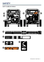
Page 7: ...hio tats Unis MWE Investments LLC Columbus Ohio 43228 Etats Unis Part N0 Num ro de pi c e Designed in Columbus Ohio USA SAFETY SAFETY LABELS AND DECALS 4 1 1 3 4 2 Made in China Fabriqu en Chine MWE I...

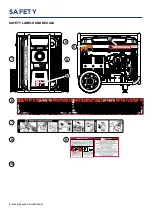
Page 8: ...8 Westinghouse Portable Power SAFETY SAFETY LABELS AND DECALS 8 7 10 8 9 6 6 7 5 10 9...

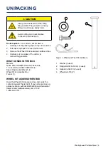
Page 9: ...ck top flaps to reveal the manual 3 Remove the Wheel Kit Accessories cardboard box 4 Carefully cut two sides of the carton to remove the generator WHAT COMES IN THE BOX Manual Quick Start Guide Mainte...

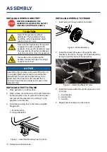
Page 10: ...mbled the wheel kit is not intended for on road use The wheel kit is designed for use on this generator only INSTALLING FEET TO FRAME 1 Place generator on a flat surface 2 Place a piece of cardboard o...

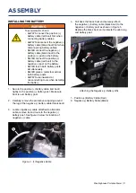
Page 11: ...attery cable black boot to the positive post on the battery NEVER connect the positive battery cable red boot to the negative post on the battery NEVER touch both battery posts simultaneously NEVER pl...

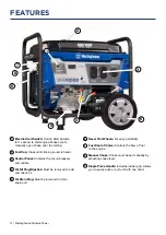
Page 12: ...breakers and outlets Oil Fill Plug Dipstick Must be removed to add and check oil Oil Drain Plug Must be removed to drain engine oil FEATURES Never Flat Wheels For easy portability Fuel Shut off Valve...

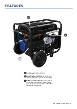
Page 13: ...l Spark Plug Boot Wire Must be removed when servicing the engine or the spark plug Muffler and Spark Arrester Avoid contact until engine is cooled down Spark arrestor prevents sparks from exiting the...

Page 14: ...h Hold in Start until engine starts Make sure to manually open choke prior to starting V F T Meter Cycles through 4 displays including frequency in hertz default blank display 00 00 total operating ho...

Page 15: ...ING Be sure the generator is properly connected to earth ground before operating The generator must be grounded to prevent electrical shock due to faulty appliances High Altitude Operation Engine powe...

Page 16: ...pliance on the top line of the chart Then select the rated amperage of the generator on the left side of the chart Where the two meet is the size of the conductor required for the application The WCG2...

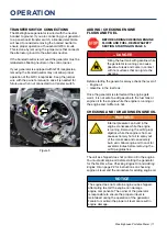
Page 17: ...e generator for the first time See Checking Engine Oil and Adding Engine Oil on page 22 for instructions on checking engine oil level and the procedure for adding engine oil NOTICE The engine does not...

Page 18: ...Before attempting to start the generator verify the following The engine is filled with engine oil See Checking Engine Oil on page 22 The generator is situated in a proper location Location Selection...

Page 19: ...e engine control switch once the engine starts could result in damage to the generator Never push the engine control switch to the START position while the engine is running this could damage the gene...

Page 20: ...il fill plug dipstick while the engine is hot can cause extremely hot oil to spray out of the crankcase and can severely burn skin Allow engine oil to cool for several minutes before removing the oil...

Page 21: ...Year Engine Oil Check Level Change Change Cooling Features Check Clean Air Filter Check Clean Replace Spark Plug Check Clean Replace Spark Arrestor Check Clean Service more frequently if operating in...

Page 22: ...stick 5 Remove oil fill plug dipstick see Figure 15 below Figure 15 Oil Fill Plug Dipstick 6 Check oil level When checking the engine oil remove the oil fill plug dipstick and wipe it clean Thread the...

Page 23: ...l authorities or reclamation facility AIR FILTER MAINTENANCE WARNING Never use gasoline or other flammable solvents to clean the air filter Use only household detergent soap to clean the air filter Cl...

Page 24: ...the spark plug boot by firmly pulling the plastic spark plug boot handle directly away from the engine see Figure 20 NOTICE Never apply any side load or move the spark plug laterally when removing th...

Page 25: ...p rag to clean all remaining surfaces TESTING GFCI OUTLETS 1 Start the generator and allow it to warm up 2 Press the test button on the GFCI outlet MAINTENANCE Test Button Reset Button CHECKING AND AD...

Page 26: ...h fuel in the tank indoors or in a poorly ventilated area where the fumes can come in contact with an ignition source such as a 1 pilot light of a stove water heater clothes dryer or any other gas app...

Page 27: ...page 23 10 Dirty plugged spark arrestor 10 Check and clean the spark arrestor 11 Stale fuel 11 Drain fuel and replace with fresh fuel see page 18 12 If trying 1 11 above does not solve the problem the...

Page 28: ...order 210004 GENERATOR COVER 210003 WGC25 25 POWER CORD 210052 30A 6 BREAKER TRANSFER SWITCH KIT MODEL WHMTS30 210075 25 CORD 30AMP TRANSFER SWITCH 210076 50A 6 BREAKER TRANSFER SWITCH KIT MODEL WHMTS...

Page 29: ...20537 BOLT M5X12 22 120517A AUTOMATIC VOLTAGE REGULATOR 23 120519 END COVER GENERATOR 24 110501 GASKET EXHAUST PIPE 25 110502 SPRING WASHER 8 26 110500 MUFFLER COMP 27 150500 FUEL TANK ASSEMBLY 27 1 1...

Page 30: ...BEARING 3 180504 THE CRANKSHAFT OIL SEAL 4 190412 PENDULUM STEM SEAL 5 190410 SWINGING ROD 6 190409 SWINGING ROD GASKET 7 190408 CHECK BACK CLIP 8 180507 OIL DRAIN BOLT 9 180508 OIL DRAIN BOLT WASHER...

Page 31: ...M10X80 52 180526 THE SPARK PLUG 53 180810 THE VALVE PUSH ROD 54 180811 WIND DEFLECTOR 55 120505 BOLT WITH DISC M6X12 NO PART DESCRIPTION 56 180527 CYLINDER CRANIUM 57 180528 CYLINDER HEAD COVER GASKE...

Page 32: ...32 Westinghouse Portable Power WH10000 SCHEMATIC...

Page 33: ...Westinghouse Portable Power 33 Version 12 17 18KD...

Reviews: