18
FEATURES
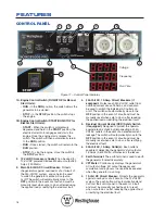
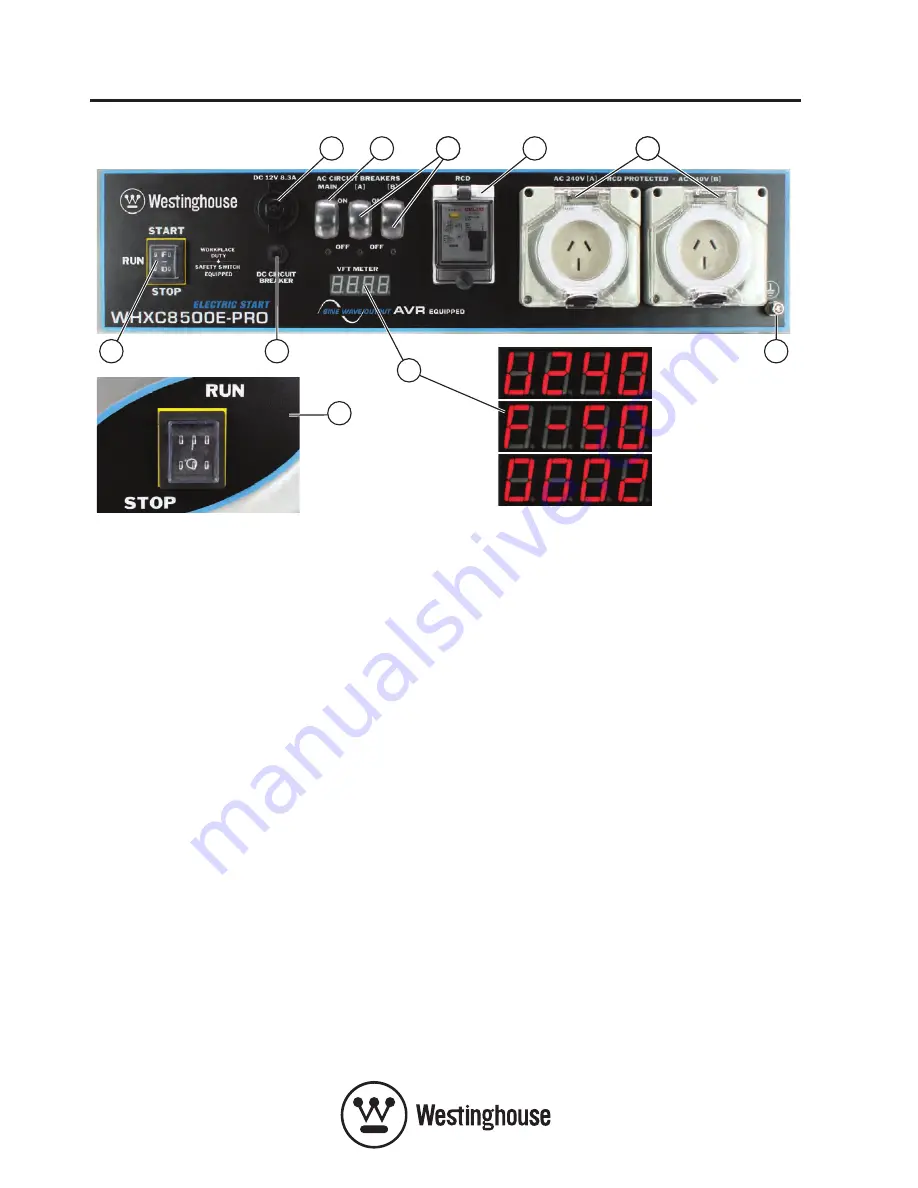
Figure 11 – Control Panel Features
Voltage
Frequency
Run Time
CONTROL PANEL
1A. Engine Control Switch (RUN/STOP for Manual
Start Units):
•
RUN - In the RUN position, the switch allows the
generator to be started.
•
STOP - In the STOP position, the switch stops
the engine.
1b. Engine Control Switch (START/RUN/STOP for
Electric Start Units):
•
START - When the switch is momentarily
depressed and held in the START position, the
electric starter motor engages and starts the
engine. Once the engine starts, release the
switch. The switch will then automatically return
to the RUN position.
•
RUN - Once started, the switch will remain in the
RUN position.
•
STOP - To stop the engine, move the switch to
the STOP position.
2. 12-Volt DC Accessory Socket: Can be used for
12-Volt DC powered devices.
Maximum output 8.3
Amps (100 Watts).
3. Main 240-Volt AC Circuit breaker: Protects
the generator against overload or short circuit of
the 240-Volt AC system, and can also be used
to switch the generator’s entire AC output on
or off. The switch will automatically move to the
OFF position in the event of a fault and must be
manually reset when safe to do so after reducing
the applied load or rectifying the electrical fault.
4. 240-Volt AC, 15-Amp Circuit breakers (if
equipped): Protect each 240-Volt AC outlet from
overload current above 15 Amps, and can also
be used to switch the individual AC outlets on
or off. The switch will automatically move to the
OFF position in the event of a fault and must be
manually reset when safe to do so after reducing
the applied load or rectifying the electrical fault.
5. Residual Current Device (RCD) Safety Switch
(if equipped): Designed to protect the operator
against electric shock by disconnecting all 240-
Volt AC outlets in the event of a detected current
leakage. The switch will automatically move to the
OFF position in the event of a fault and must be
manually reset when safe to do so after rectifying
the electrical fault.
6. 240-Volt AC, 15-Amp Outlet(s): Each outlet is
capable of delivering the generator’s full output or
15 Amps
(3,600 Watts),
whichever is the lesser.
7. Earth Terminal: The earth terminal is used to earth
the generator for electrical safety.
8. VFT Meter:
Continuously displays the generator’s
AC output voltage, AC output frequency and
cumulative running hours in a repetitive sequence
when the generator is running.
9. 12-Volt DC Circuit breaker:
Protects the generator
against overload or short circuit of the 12-Volt DC
system. The push button will automatically extend
out from the control panel in the event of a fault
and must be manually pushed back in to reset
when safe to do so after reducing the applied load
or rectifying the electrical fault.
1A
5
4
5
6
1b
5
2
3
9
7
8
Summary of Contents for WHXC3750
Page 4: ...4...
Page 55: ...55 NOTES...


