52
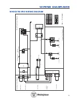
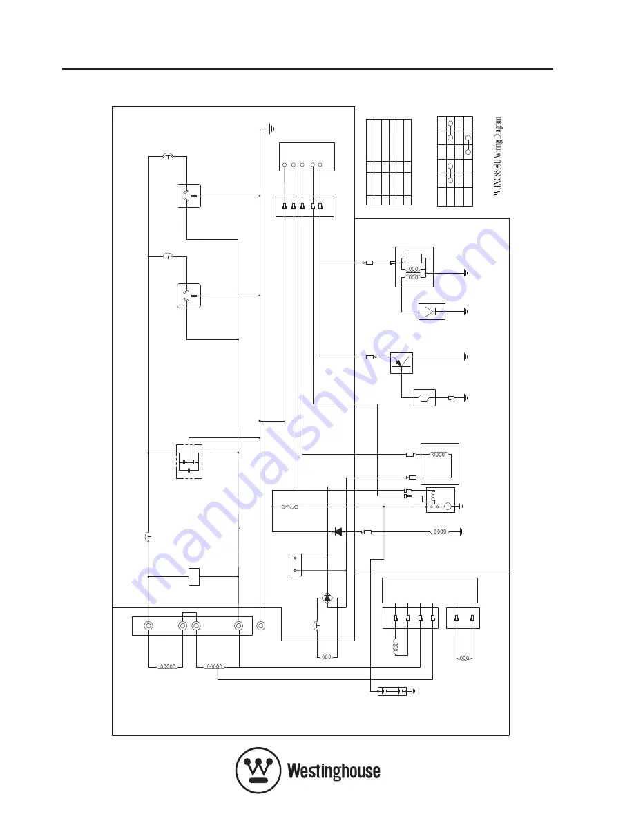
WIRING DIAGRAMS
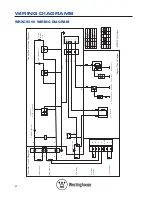
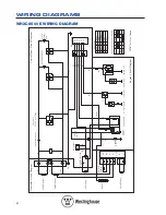
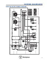
WHXC8500E Wiring DiagraM
AVR
W
R
G
W
Bu
Bu
G
R
W
Y
JG
IG
FS
E
S/P
Gr
Engine S
witch
Diagram
C
irc
ui
t
Generator
Diagram
C
irc
ui
t
Panel
C
on
tro
l
Diagram
C
irc
ui
t
Engine
1
W
inding
Ma
in
2
W
inding
Ma
in
W
inding
Excitation
W
inding
Fie
ld
Sol
en
oi
d
Fu
el
Switch
Level
Oil
Amplif
ier
Plug
Sp
ar
k
Coil
Ignition
Gr
Bl
Y/G
G
Y/G
Bl
Output
DC
W
R
O
O
R
W
Colour
Wi
re
ST
Bl/W
Bl/W
2×
47
00
pF
+
0.
33
uF
Capacitor
s
15
A
Breake
r
Circuit
15
A
Breake
r
Circuit
DC W
inding
M
Battery
Y/G
Diagram
Contac
t
Switch
Engin
e
30
A
Breake
r
Circuit
10
A
Breake
r
Circuit
White
W
Green
Red
Blue
Black
Bl
Y
ellow
Y
Bu G
R
Grey
Gr
Br
Brown
Orange
O
LB
Light Blue Light Green
LG
Pink
P
JG
FS
ST
E
IG
OFF
ON
ST
A
R
T
Fu
se
5A
W
Br
Charge Coil
St
ar
te
r
Mo
to
r
Bl
Bl
Bl
VFT
Summary of Contents for WHXC3750
Page 4: ...4...
Page 55: ...55 NOTES...

