CONNECTION
2
INTRODUCTION
The Westinghouse WHXC8500E-AS generator as
originally supplied is configured for connection to
portable tools and appliances or a fixed electrical
installation by means of detachable plug and socket
outlet connection(s) to either or both of its 240-Volt
AC, 15-Amp outlets
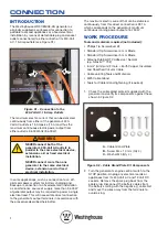
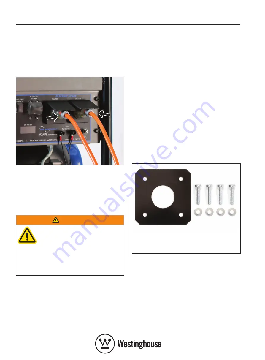
(see Figure S1)
.
Figure S1 – Connection to the
240-Volt AC, 15-Amp Outlets
The maximum electric current that can be delivered
continuously from either of the generator’s 240-
Volt AC outlets is 15 Amperes (15 A) and thus the
maximum continuous electric power output from
either outlet is 3,600 Watts (3,600 W).
WARNING
NEVER connect both of the
generator’s 240-Volt AC outlets in
parallel to the same electrical device,
extension cord or fixed electrical
installation.
NEVER connect more than one
generator to the same electrical
device, extension cord or fixed
electrical installation.
In some applications, such as connection to an off-
grid solar power system for battery charging and
backup or connection to a fixed electrical installation
as an alternative source of supply, more than 3,600 W
of generator output may be required to power a single
electrical load. This will necessitate direct connection
to the generator’s output terminals in accordance with
the procedure described hereinafter.
The maximum electric current that can be delivered
continuously from this direct connection is 28.1 A,
which corresponds to the generator’s maximum
continuous running power output of 6,750 W.
WORK PROCEDURE
Tools and materials required (not included):
• Phillips Tip Screwdriver #2
• Standard Tip Screwdriver 4 mm Blade
• Standard Tip Screwdriver 5 mm Blade
• Silicone Rubber RTV Adhesive / Sealant
(e.g. Silastic™ 732)
• 6 mm
2
(minimum) 2 Core + Earth Copper, Insulated
and Sheathed Circular Cable
• Cable Jointing Tools and Materials
• M25 Cable Gland
• Tools for Cable Gland tightening (if required)
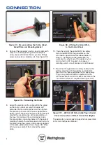
1. Check the cable gland plate kit supplied with the
generator and verify its components against those
shown in
Figure S2.
Figure S2 – Cable Gland Plate Kit Components
2. Turn the generator’s engine control switch to the
STOP position. Unplug any electrical cords or
appliances from its 240-Volt AC and 12-Volt DC
sockets. Remove the spark plug boot from the
spark plug. Disconnect the battery cables from
the battery starting with the negative (-) cable first
and move the wires away from the terminals to
avoid arcing.
A
– Cable Gland Plate
B
– Screw M4 x 10 mm (Qty 4)
C
– Washer M4 (Qty 4)


