CONNECTION
3
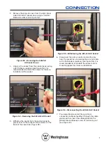
3. Remove the snap-on cover from the right-hand-
side 240-Volt AC socket only using a small flat
blade screwdriver
(see Figure S3)
.
Figure S3 – Removing the 240-Volt
AC Socket Cover
4. Unscrew the socket from the control panel using
a #2 Phillips screwdriver
(see Figure S4)
. It is
recommended to retain the screws for future re-
installation of the socket.
Figure S4 – Removing the 240-Volt AC Socket
5. Withdraw the socket from the control panel to
give access to the wiring terminal screws on the
back of the socket
(see Figure S5)
.
Figure S5 – Withdrawing the 240-Volt AC Socket
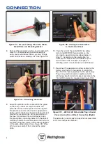
6. Disconnect the active, neutral and earth wires
from the socket by unscrewing the wire terminals
with a flat blade screwdriver
(see Figure S6
). It is
recommended to retain both the socket and its
mounting gasket for future re-installation.
Figure S6 – Disconnecting the 240-Volt AC Socket
7. Pre-assemble one end of the new direct-
connection cable by feeding it through the cable
gland and then insert the cable gland into the
gland plate and loosely screw on its locking nut
(see Figure S7)
.


