CONNECTION
4
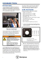
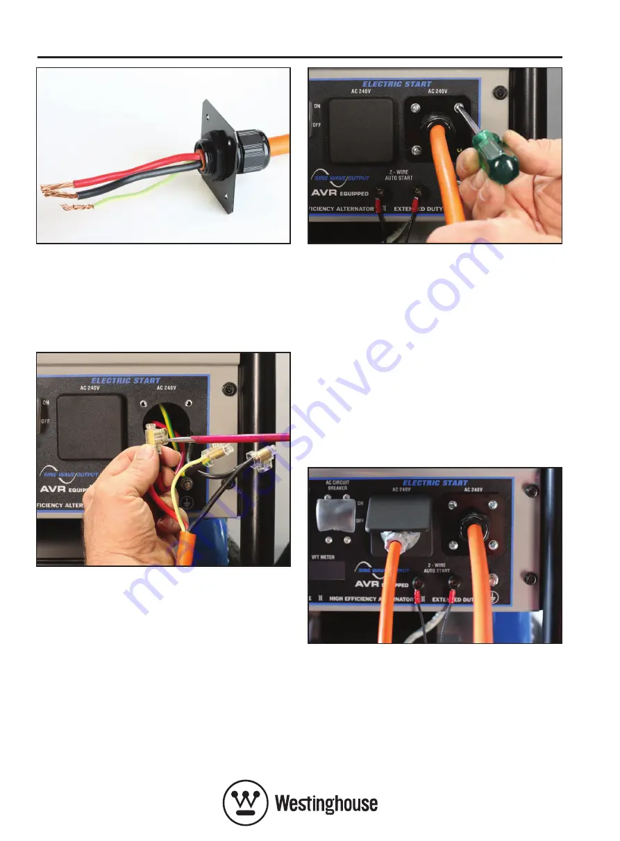
Figure S7 – Pre-assembling the Cable, Gland,
Gland Plate and Mounting Gasket
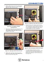
8. Connect the generator’s active, neutral and earth
wires to the corresponding cable conductors
using your preferred method, e.g. crimp fittings,
screw connectors, soldering, etc.
See Figure S8
.
Figure S8 – Connecting the Cable
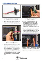
9. Adjust the position of the cable within the gland
so that only a minimum length of cable will
protrude into the control panel and then tighten
the gland by hand or with a tool as appropriate.
Apply a small continuous bead of silicone sealant
around the circumference of the gland plate on
the face that will abut the control panel. Align
the gland plate’s mounting holes with the socket
mounting holes in the control panel and then affix
the plate using the screws and washers supplied
in the cable gland plate kit
(see Figure S9)
. Wipe
off any excess sealant from around the gland
plate.
Figure S9 – Affixing the Gland Plate
to the Control Panel
10. The other end of the cable MUST be safely
terminated BEFORE the generator can be
returned to operation as described below in
Step 11. According to the application, for
example, the other end of the cable may be
terminated in a 32 A socket, changeover /
isolating switch, circuit breaker or switchboard.
11. Reconnect the generator’s battery cables to the
battery starting with the positive (+) cable first.
Re-attach the spark plug boot to the spark plug.
Plug in any electrical cord or appliance to the
left-hand-side 240-Volt AC socket and also to the
12-Volt DC socket, as required
(see Figure S10)
.
Figure S10 – 240 Volt AC Detachable Plug & Socket
Connection (Left) and Direct Connection (Right)
The generator is now ready for operation as described
in the main Instruction Manual.


