WESTLOCK CONTROLS CORPORATION
280 MIDLAND AVENUE, SADDLE BROOK, NJ 07663 TEL: 201-794-7650 FAX: 201-794-0913
www.westlockcontrols.com
4/06/10
TECH-385Q/D.W.O. 19105
Page 3 of 5
2.2. Calibration
Note 1:
Switch actuation can be confirmed using a signal detection device
such as a multimeter or ohmmeter, set for “continuity”.
Note 2:
For NAMUR P+F NJ2-V3-N type sensors, use test meter, P+F model
#1-1350 or equivalent to check sensor actuation and calibration. If the proper
meter is not available, contact the factory for additional assistance with the
test procedure.
Note 3:
Adjust cams by hand by pushing/pulling the cam against the shaft
spring to disengage from the mating spline, rotating to adjust and re-engaging
firmly onto spline.
Required Tools:
Signal detection device (see note 1); slotted screw driver for
cover screws (M4, #10 or 5/16 by model)
Switch Adjustment (two switches):
1.
Remove unit cover as follows: loosen (but do not remove) captive screws,
rotate cover slightly to grip corners, pull firmly.
DO NOT PRY COVER WITH TOOLS.
2.
With valve in the closed position, adjust bottom cam until bottom switch
(#2) actuates.
3.
Stroke valve to the open position, adjust top cam until top switch (#1)
actuates.
4.
Cycle actuator several times to confirm proper switch indication at each
end of stoke. Finely adjust cams if necessary.
5.
Skip to Field Wiring section or replace unit cover, applying approximately
20 in-lbs of torque to cover screws.
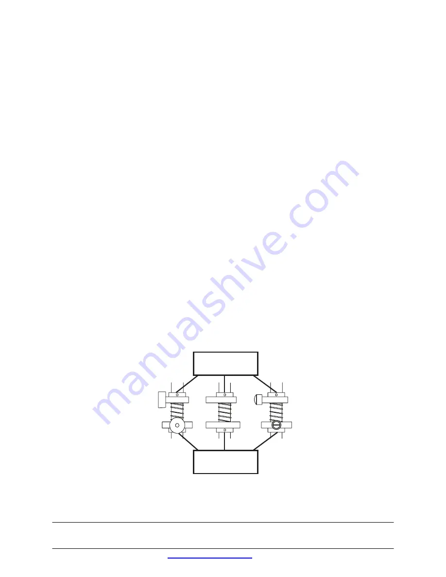
TOP CAM
TOP CAM
PUSH DOWN, TURN
PUSH DOWN, TURN
& RELEASE
& RELEASE
MAGNUM & MAGPAC
MAGNUM & MAGPAC
PROXIMITY
PROXIMITY
SWITCH
SWITCH
MECHANICAL
MECHANICAL
SWITCH
SWITCH
iNDUCTIVE
iNDUCTIVE
PROXIMITY
PROXIMITY
SENSOR
SENSOR
BOTTOM CAM
BOTTOM CAM
LIFT UP, TURN
LIFT UP, TURN
& RELEASE
& RELEASE


