5/12/2017
TECH-538/D.W.O. 23160
Page 19 of 189
Step 2.
Press fit the inner beacon to the inner beacon coupler. The inner beacon needs to be properly oriented.
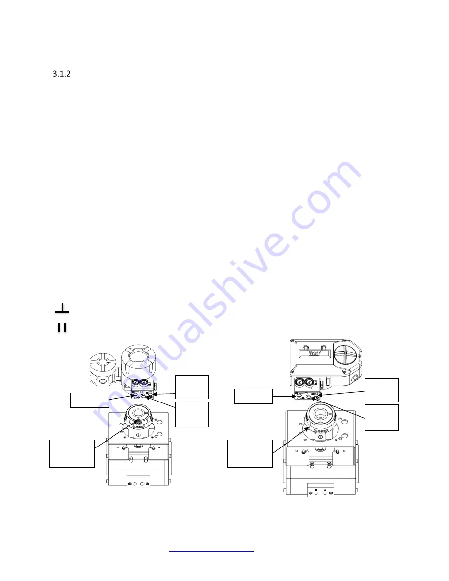
Use the symbols on the top of the inner beacon to mount as shown in Condition 1 or Condition 2.
The reference used for the magnet position is the ICoT, not the actuator. Please note that the magnet
orientation is with reference to the positioner manifold.
Condition 1:
Actuator fails in a clockwise direction.
Spring Return
Output Port 2 is plugged
Output Port 1 is piped to turn the actuator counter
clockwise
Double Acting
Output Port 2 is piped to turn the actuator clockwise
Output Port 1 is piped to turn the actuator counter
clockwise
Magnet position (with actuator in clockwise position)
Placed at 6:00 (bottom)
Placed at 3:00 (right)
Figure 3-2 - Rotary – Direct – Condition 1
(ICoT 6000)
`
Figure 3-3 - Rotary – Direct – Condition 1
(ICoT 5000)
SUPPLY
PORT
2
PORT
1
BEACON
SYMBOLS
PORT
2
PORT
1
BEACON
SYMBOLS
SUPPLY


