1ZKY1A and 1ZKY3A
2
Westward Operating Instructions and Parts Manual
Heavy Duty Transmission Jack
Study, understand and follow all
instructions before operating this device. Do not
exceed rated capacity. Use only on hard, level
surfaces. Adequately support the vehicle before
starting repairs. Use of this product is limited to
the removal, installation, and transportation in
the lowered position, of transmissions, transfer
cases, and transaxles. Only attachments and/or
adapters supplied by the manufacturer shall be
used. Failure to heed these markings may result
in personal injury and/or property damage.
Assembly
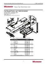
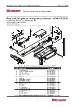
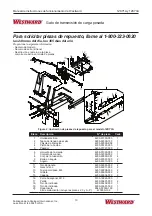
(ref. Figures 1 & 2)
1. Two pieces of aux. fixed bracket assembly and a
one-piece handle should be included in package.
2. Attach either one of the two aux. fixed assemblies
to the saddle, and secure by hex bolts and
washers provided. Then apply the same
procedure for the other assembly.
3. Occasionally hydraulic jacks become air bound
and will not function properly. To correct this
condition, perform Bleeding/Venting Trapped Air
procedure.
4. Check for proper oil level (ref. Adding Oil, pg. 2),
adjust as needed. DO NOT OVERFILL. Reinstall
oil filler plug.
Preparation
1. Verify that the product and application are
compatible.
2. Before using this product, read the operator's
manual completely and familiarize yourself
thoroughly with the product, its components and
recognize the hazards associated with its use.
3. To familiarize yourself with basic operation, turn
the release valve knob:
a. Clockwise until firm resistance is felt to further
turning. This is the ‘CLOSED’ release valve
position used to raise the saddle.
b. Counter-clockwise, but no more than 1/2 turn
from the closed position. This is the ‘OPEN’
release valve position used to lower the
saddle.
4. With saddle fully lowered and release valve fully
closed, pump the operating handle. If lift arm
responds immediately, jack is ready for use. If
jack does not respond, follow Bleeding/Venting
Trapped Air instruction below.
5. Ensure that jack rolls freely. Raise and lower
the unloaded saddle throughout the lifting
range before putting into service to ensure
the pump operates smoothly. Replace worn or
damaged parts and assemblies with authorized
replacement parts only.
Bleeding/Venting Trapped Air
With the release valve in the OPEN position (step
3b. above) and with saddle fully lowered, locate
and remove the oil filler plug/screw. Pump 6 to 8 full
strokes. This will help release any pressurized air
which may be trapped within the reservoir. Proper
oil level will vary from just covering the ram cylinder
to 3/16” (0.48 cm) above it as seen from the oil filler
hole. Reinstall the oil filler plug/screw.
Operation
Off-center loads and loads lifted
while jack is not level may damage the jack or
cause personal injury.
REMOVING TRANSMISSION/DIFFERENTIAL
1. Close the release valve by turning the release
knob clockwise.
2. Operate the jack by pumping the jack handle to
desired height.
3. Adjust the saddle in side position and tilting angle
to best fit to the shape of transmission/differential.
4. Secure the transmission/differential by chain and
tighten properly.
5. After removing all of the appropriate bolts and
fasteners which securing the load to vehicle,
carefully position and lower the load to the lowest
practical height. Move load to desired workplace.
This is a removal/installation
device only. While conducting maintenance, the
load must be supported by other means.
INSTALLING TRANSMISSION/DIFFERENTIAL
1. Place transmission/differential on jack saddle and
properly secure by chain.
2. Cautiously pump jack handle to lift up the
transmission/differential to desired height.
3. After all securing bolts are properly fastened, open
the release valve by turning release knob
counterclockwise to lower the jack to minimum
height.
Avoid shock loads created by
quickly opening and closing the release valve as
the load is being lowered. Shock loads can
create dangerously high operating pressures
within the hydraulic system, causing system
failure and resulting in personal injury and/or
property damage.
Maintenance
NOTICE:
Use only premium quality hydraulic jack oil
Avoid mixing types of oil. Do not use break fluid,
alcohol, glycerin, motor oil etc. Improper fluid can
cause serious internal injury to the jack, rendering it
inoperative.
ADDING OIL
1. Position the jack on level ground with saddle fully
lowered, remove oil filler plug.
2. Oil level should be within 3/8” (0.95 cm) of filler
hole. DO NOT OVERFILL. If overfilled, jack will
not lower to minimum height. If underfilled, jack
will not reach maximum height. Adjust fluid level
as needed. Always reinstall oil filler plug before
use.


