60
5. Control board indicators instruction
FLG-200HD,FLG-300HD and FLG-400HD plasma power source use same PCB
,
SQK-A1,SQK-B1
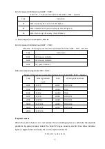
gas console use same PCB. There are different indicators on board,which helps find out
problems easily.
1)
Plasma power source FLG-200HD,FLG-300HD,FLG-400HD
Main control board AP1
(
PL01
)
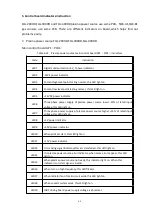
Table 6-14 Plasma power source main control board AP1
(
PL01
)
indicators
Code
Instruction
LED1
Digital communi5V_T power indicator.
LED2
-15V1 power indicator.
LED3
Coolant high level point testing normal, this LED light on.
LED4
Coolant low level point testing normal, this LED light on.
LED5
+24VDC power indicator.
LED6
Three phase power supply of plasma power source lower -15% of rated input
voltage, this LED light on.
LED7
Three phase power supply of plasma power source 15% of rated input
voltage, this LED light on.
LED8
+5V power indicator.
LED9
+15V1 power indicator.
LED10
When pilot arc start, this LED light on.
LED11
+15V power indicator.
LED13
It is moving signal indicator,after arc transferred, this LED light on.
LED14
It is plasma power source error indicator, when some errors appear, this LED
light on.
LED15
When plasma power source not ready, this indicator light on. When this
indicator is on,start signal is invalid.
LED16
When turn on high frequency, this LED flickers.
LED17
When radiator fan of main circuit work, this LED light on.
LED18
When coolant system work, this LED light on.
LED19
IGBT driving board power supply voltage is abnormal.
Summary of Contents for FLG-200HD
Page 9: ...5 Figure 2 1 System connection diagram ...
Page 43: ...39 Figure 5 2 SQK A1 front panel function Figure 5 3 SQK B1 front panel function ...
Page 74: ...70 4 System wiring diagram Figure 7 1 System wiring diagram ...
Page 77: ...73 2 Main circuit wiring diagram 2 Figure 7 4 FLG 200HD Main circuit wiring diagram 2 ...
Page 81: ...77 6 HF striking diagram Figure 7 8 HF striking diagram ...


