background image

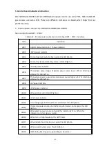
62

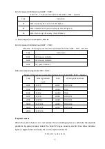
Status ID

Instruction

000

System on power

002

Blowing status

003

Standby status

004

Preflow

005

Pilot arc

006

Transferred arc

007

Gradually up

008

Stable cutting

009

Gradually down

010

Cut automatically

012

Cutflow testing

014

Machine shut down

016

Debug

020

Preflow testing

024

Gas leakage testing

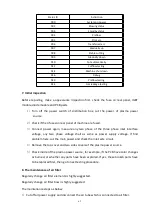
7. Initial inspection

Before repairing, make a appearance inspection first, check the fuse on real panel, IGBT
module,diode module and PCB parts.

1)

Turn off the power switch of distribution box, cut the power of plasma power

source.

2)

Check if the 4 fuses on rear panel of machine are fused.

3)

Connect power again, measure any two phase of the three phase inlet interface
voltage, any two phase voltage shall as same as power supply voltage. If find
problem here, cut the main power and check the inlet wire circuit.

4)

Remove the top cover and two sides covers of the plasma power source.

5)

Check inside of the plasma power source, for example, if the PCB have color changes
as burned, or whether any parts have been explored. If yes, these broken parts have
to be replaced first, then go to next testing procedure.

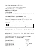
8. The maintenance of air filter

Regularly change air filter elements is highly suggested.

Regularly change air filter bowl is highly suggested.

The maintenance steps as below:

1)

Cut off all power supply and disconnect the air tube which is connected to air filter.

Summary of Contents for FLG-200HD

Page 1: ...FLG 200HD 300 400HD FINE PLASMA CUTTING MACHINE SQK A1 SQK B1 MANUAL GAS CONSOLE MANUAL INSTRUCTION PLEASE READ CAREFULLY BEFORE OPERATION ...

Page 2: ...k before you act and be careful Special Attention Very Important 1 AVOID FALLING DOWN WHEN THE WELDING CUTTING MACHINE IS PLACED ON THE INCLINED SURFACE 2 IT CAN NOT BE USED FOR UNFREEZING PIPELINES 3 THE INGRESS PROTECTION CLASS OF THIS SERIES MACHINE IS IP21S AND IT IS NOT SUTABLE FOR WORKING IN THE RAIN 4 THIS MACHINE WITH SHARP DROP STATIC EXTERNAL CHARACTERISTIC THE RATED DUTY CYCLE IS 100 ME...

Page 3: ... 4 Manual gas console SQK B1 13 5 HF Box QFK D1 13 6 System gas supply requirements 14 7 Requirements of torch coolant 15 IV Installation 18 1 Acceptance of delivery 18 2 Product defect solution 18 3 Installation requirement 18 4 Noise level 19 5 System installation Figures 19 6 Grounding connection and shield installation operation 21 7 Plasma power source installation Part A in Figure 4 2 system...

Page 4: ...to optimize cutting quality 43 VI Maintenance 47 1 Operation process 47 2 Gas blowing process 48 3 Gas console solenoid valve operation 48 4 Trouble shooting and error code 52 5 Control board indicators instruction 60 6 System status 61 7 Initial inspection 62 8 The maintenance of air filter 62 9 The maintenance of cooling system 63 10 Gas leakage testing 64 11 Preventive maintenance 66 VII Append...

Page 5: ... voltage is supposed to be two times of welding voltage while the grounding mode is not clear While working high above the ground or other places having the risk of falling please be sure to wear safety belt to avoid losing balance caused by electric shock 2 Arc Use an arc welding mask to protect your eyes and skin from sparks and the rays of the arc pay special attention to the filter glass which...

Page 6: ...intenance and repair so that avoid accident HUAYUAN welding equipment is Ι class safeguard equipment please install the equipment in accordance with the manufacturer s recommendations by specific persons Ground the equipment perfectly in accordance with the manufacturer s recommendations 7 Power For engine driven welding and cutting equipment Work in ventilated place or outdoors Do not add fuel ne...

Page 7: ...e is no person below the welding machine and remind people passing by at any moment Do not move the hoist too fast 10 Noise HUAYUAN Welding Machine Manufacture reminds users Noise beyond the limit over 80 db can cause injury to vision heart and audition depending on oneself Please consult local medical institution Use the equipment with doctor s permission would help to keeping healthy II Product ...

Page 8: ...nd switch gas need to connect the required gas to gas input interfaces manually And gas console automatically distributes the required gas flow 3 HF box QFK D1 High frequency box mainly used to generate high frequency pulse to generate pilot arc When the pilot arc approaches the work piece the main arc is generated then pilot arc close Another function is to receive commands from the manual gas co...

Page 9: ...5 Figure 2 1 System connection diagram ...

Page 10: ...n of high frequency box and plasma power source which highly reduces the high frequency disturb and get 100 arc starting success rate 5 Various of communication control connector can easily work with different type of CNC control systems 4 Usage 1 It s suitable for CNC cutting of carbon steel stainless steel and aluminum etc 2 It s widely used in manufacturing of boiler chemical pressure vessels s...

Page 11: ...e gas and flammables and explosives Do not use it in open air and in rain 2 Environment temperature range is 10 40 and 20 55 when delivery and storage 3 Required air relative humidity should 90 at 20 50 at 40 4 The dust acid corrosive gas or substances around shall not exceed the normal content except those produced in the cutting process 5 Use it under altitude lower than 1000m 6 The gradient of ...

Page 12: ...ltage A V 200 200 Rated output current range A 15 200 Arc striking mode Non contact Quality cutting thickness Carbon steel mm 25 1 Piercing cutting thickness Carbon steel mm 25 2 Max cutting thickness mm 50 3 Insulation grade F Cooling mode Air cooling Protection grade IP21S Note above 1 2 3 cutting thickness is working with the parts listed in this instruction manual even though can cut thicker m...

Page 13: ...3 2 FLG 200HD Static external characteristic 2 Plasma power source FLG 300HD 1 Basic parameters Table 3 2 FLG 300HD technical parameters Item Unit Parameter Input power V Hz 3 380 15 50 60 Rated input current A 110 Rated input capacity kVA 72 4 Rated open circuit voltage V 370 Power factor 0 92 Efficiency 93 ...

Page 14: ... 2 Max cutting thickness mm 64 3 Insulation grade F Cooling mode Air cooling Protection grade IP21S Note above 1 2 3 cutting thickness is working with the parts listed in this instruction manual even though can cut thicker material but recommend cutting higher 80 materials thickness within 38mm and start cutting from edge Piercing cutting should not exceed 38mm 1 Dimension and weight Figure 3 3 FL...

Page 15: ...100 40 Rated output current voltage A V 400 200 Rated output current range A 15 400 Arc striking mode Non contact Quality cutting thickness Carbon steel mm 50 1 Piercing cutting thickness Carbon steel mm 50 2 Max cutting thickness mm 80 3 Insulation grade F Cooling mode Air cooling Protection grade IP21S Note above 1 2 3 cutting thickness is working with the parts listed in this instruction manual...

Page 16: ... and weight 3 Static external characteristic Figure 3 6 FLG 400HD Static external characteristic 3 Manual gas console SQK A1 1 Manual gas console SQK A1 has 4 gas input interfaces they are Air N2 or Ar O2 H35 or F5 2 Max input gas pressure is 132 PSI 0 9 MPa ...

Page 17: ...mension and weight 4 Manual gas console SQK B1 1 Manual gas console SQK B1has 2 gas input interfaces they are Air and O2 N2 Ar 2 Max input gas pressure is 132 PSI 0 9 MPa 3 Dimension and weight as Figure 3 8 Figure 3 8 SQK B1 Dimension and weight 5 HF Box QFK D1 ...

Page 18: ...ty 99 995 H35 65 Ar 35 H2 0 8MPa 8bar 115 PSI 70 L min F5 Nitrogen hydrogen Purity 99 98 F5 95 N2 5 H2 0 8MPa 8bar 115 PSI 70 L min Ar Argon Purity 99 99 Clean dry and oil free 0 8MPa 8bar 115 PSI 70 L min Note The Air in above table should accordance with the ISO standard 8573 1 grade as following Solid particle grade Grade 1 0 1 0 5μm particle not exceed 100pc 0 5 5 0μm particle not exceed 1pc p...

Page 19: ... 400A O2 Air N2 Air N2 Air H35 N2 H35 N2 Table 3 6 SQK B1 gas type GAS TYPE Low carbon steel STAINLESS STEEL ALUMINUM Plasma gas Shield gas Plasma gas Shield gas Plasma gas Shield gas 30 50A O2 O2 N2 N2 Air Air 80A O2 Air 130A O2 Air N2 N2 Air Air 200A O2 Air N2 N2 N2 N2 260A O2 Air N2 Air N2 Air 300A O2 Air N2 Air N2 Air 400A O2 Air N2 Air N2 Air 7 Requirements of torch coolant When delivery the ...

Page 20: ...damage coolant system Use pure water in the coolant compound to prevent corrosion of the cutting torch cooling system 1 The Huayuan standard coolant liquid is suitable to work in temperature between 12 and 40 10 104 The Huayuan standard coolant liquid of this cutting system is composed by 69 9 water 30 ethylene propylene glycol and 0 1 benzotriazole If temperature is beyond of the range please ref...

Page 21: ...of pure water which meet the below purity standard and benzotriazole with percentage of 300 1 As a corrosion inhibitor benzotriazole is suitable for copper cooling system included in plasma system 4 Water purity Table 3 7 Specification of water purity Specification of water purity Conductivity μS cm 25 hour Electrical resistivity mΩ cm 25 hour NaCl content Unit ppm CaCO3 content Unit ppm Pure wate...

Page 22: ...are received in good condition if any parts or accessories lost please contact the supplier Please check whether any accessories are damaged during transportation If and damages refer to the product defect handling section 2 Product defect solution Treatment of defects such as appearance damages during transportation or other damages that affect the use of product If the product is broken on the w...

Page 23: ...tection devices Please also refer to the chapter noise hurts hearing in the safety section of this manual 5 System installation Figures Note Check all the parts before connect the cables and hoses components can be placed according to the system installation diagram shown in this section Ground all system components For the grounding method please refer to the section grounding and shield installa...

Page 24: ...20 Figure 4 2 System installation diagram 1 System components A Plasma cutting power source Inverter fine plasma cutting machine FLG 200 300 400HD ...

Page 25: ...ole G Composite cable from manual gas console to HF box Control cable HF box solenoid valve Connecting hose of working gas H Plasma torch cable I Work piece cable Called as cutting ground cable J Control cable from plasma power source to CNC K Control cable of multi plasma power source L Gas supply hose Figure 4 2 is manual gas console SQK A1 O2 hose N2 or Ar hose 11 Air hose 12 Argon hydrogen H35...

Page 26: ...machine grounding bus separately The grounding rod should be installed within 6 meters of the cutting table to comply with national and local electrical regulations The PE grounding cable needs to be connected to the grounding bus or equivalent potential cable located on the cutting table All PE grounding cables are yellow and green wires For better shielding well connect the cutting machine CNC c...

Page 27: ...d maintenance leave one meter space at each side of the cutting power supply machine The cooling fan draws cold air from the front panel and discharge at the rear Do not put any filter equipment at the air inlet it will affect cooling efficiency Do not put the cutting machine at tilting slop more than 10 degree to avoid dumping 2 Power supply installation requirements of plasma cutting power sourc...

Page 28: ...ctric kills When install the cable the switch must be cut OFF Obey the regional or national safety requirements Remove the power junction box on the plasma power rear panel and connect the power cable to the input terminals Connect the grounding conductor PE to the grounding terminal marked on the plasma power rear panel Make sure the switch is OFF during the whole installing process Connect all c...

Page 29: ...box installation Part C in Figure 4 2 system installation Figure HF Box 1 HF box should installed on the CNC torch moving body close to the cutting torch to ensure that the length of the plasma gas pipe and protective gas pipe connected with the plasma cutting torch is not more than 1 8m 2 Reserve a certain space for maintenance Check Figure 4 4 for the location of the installing holes ...

Page 30: ... 5 HF box and plasma torch connection 10 Other cables and connecting pipes 1 Composite cable between plasma power source to HF box Part E in Figure 4 2 system installation Figure Other cables and connecting pipes Power cable of HF box Cable in Figure 4 2 system installation Figure The power cable of HF box should connect with socket X3 in plasma power source machine and socket XS13 in HF box the c...

Page 31: ...le pin signals of manual gas console Power cable pin signals of manual gas console Plug Pin Signal 1 Ground cable 2 CAN L 3 CAN reference 4 Not use 5 Not use 6 Not use 7 CAN H 8 Not use 9 Not use Manual gas console power cable Cable in Figure 4 2 system installation Figure The power cable of manual gas console should connect with socket X2 in plasma power source machine and socket XS9 in manual ga...

Page 32: ...fire Plasma gas preflow 6 AC 120V back Plasma gas preflow 7 AC 120V fire Plasma gas cut flow 8 AC 120V back Plasma gas cut flow 9 AC 120V fire Plasma gas pressure relief 10 AC 120V back Plasma gas pressure relief 11 Ground cable 12 Not use Working gas connection pipe Cable in Figure 4 2 system installation Figure The working gas connection pipe between manual gas console and HF box include 4 worki...

Page 33: ...use 14 15 Output Not ready E Not ready C Inform CNC plasma cutting system not ready Input 16 17 Output Move 2E Move 2C Inform CNC arc transferred already default action 1 signal Input 18 24VDC reference 19 20 Output Move 3E Move 3C Inform CNC arc transferred already default action 1 signal Input 21 22 Output Move 4E Move 4C Inform CNC arc transferred already default action 1 signal Input 23 24 Inp...

Page 34: ... The circuit control and connection please refer to the input circuit figure of this chapter Action signal is for option for multi plasma power source use Choose the power of cutting machine input and output from machine or from outside according to the CNC system The plasma power source provide voltage is 24VDC max output 200mA When outside CNC system offer input and output power require the max ...

Page 35: ... signal Arc voltage output cable plug signal Plug pin Signal 1 Arc voltage signal 2 Arc voltage signal 11 Plasma power source output signal diagram Figure 4 6 4 7 4 8 is the connection and process diagram of plasma output signal in Table 4 5 1 Logic connector high electrical level Figure 4 6 Logic connector high electrical level 2 Logic connector low electrical level Figure 4 7 Logic connector low...

Page 36: ... signal in Table 4 5 1 Potentiometer interface Use plasma power source inside 24VDC power Default Figure 4 9 Plasma power source inside 24V potentiometer interface Use CNC power 24VDC Pay attention to the XS16 XS17 short connect position of control cable PL01 Figure 4 10 Outside supply 24V potentiometer interface 2 Optocoupler interface Use plasma power source inside 24VDC power Default ...

Page 37: ... 24V optocoupler interface 13 Plasma torch installation 1 Plasma torch installation The cutting machine can work with different brand of plasma cutting torch details refer to the torch manual 2 Torch cable and HF box connection Make sure the gas hose length from plasma gas and shield gas output connector of HF box to torch head less than 1 8m 3 Install the plasma torch on CNC cutting table ...

Page 38: ...requirement chapter Don t fill too much coolant For different torch cable length and the HF box installation distance the coolant require capacity is 20 35L the coolant tank capacity is 20L fulfil the coolant as following steps when first use Step 1 Full fill the tank with coolant Step 2 Power on the plasma power source Error code 060 Coolant not enough maybe appear on manual gas console Then pres...

Page 39: ...MPa Turn on the plasma power source power After blowing and clean the gas console press knob 7 select preflow indicator on system start to blow During blow process adjust the gas regulator to make Shield gas pressure to 0 83MPa Press the knob 7 on manual gas console select the cutflow indicator on system start to blow Adjust the gas regulator to make plasma gas pressure to 0 83MPa Press the knob 7...

Page 40: ... this manual and have to check again as follow steps Plasma torch checking WARNING Before operation please read carefully safety chapter Turn off power before operate the following 1 Turn off the power of contribution box and cut the power switch of the plasma power source 2 Take down consumables from plasma torch and check if there is some wearing or damage Please put all consumables on clean dry...

Page 41: ... See Figure 5 1 The default setting is one CNC control one cutting machine N54 XS16 XS17 N27 N52 N39 ON 1 2 ON 2 3 4 5 6 7 8 1 ON 2 3 4 1 短接 Figure 5 1 PL01 Hardware Default Settings In Figure 5 1 the default setting of N27 toggle switch means this plasma power source machine use MOVE 1 as running signal output all other move signal has no any of functions on this machine The default setting of N5...

Page 42: ...7 toggle switch pin 1 2 to ON position other 6 toggle switch pin to opposite of ON position MOVE 2 signal is to pull the N27 toggle switch pin 3 4 to ON position and other 6 pin to opposite of ON position The rest can be done in the same way RS422 communication matching resistor RX set this setting is not for all users but based on users system installation environment and decide if it s necessary...

Page 43: ...39 Figure 5 2 SQK A1 front panel function Figure 5 3 SQK B1 front panel function ...

Page 44: ...ns are totally same SQK A1 works with cutting gas O2 O2 O2 Air Air Air N2 Air N2 N2 H35 N2 F5 N2 SQK B1 works with cutting gas O2 O2 O2 Air Air Air N2 Air N2 N2 2 Rear panel function Figure 5 4 SQK A1 back rear function Figure 5 5 SQK B1 rear panel function 3 Front panel function instruction Table 5 1 Front panel function instruction ...

Page 45: ...Select 3 digital tube display knob Knob 8 select AMPS indicator on means the digital tube display the current value In standby mode it displays the set current value Rotate the encoder to adjust the set current value When cutting it displays the actual cutting current value This value is for reference the actual output current maybe 3A difference with the set current Knob 8 select STATUS indicator...

Page 46: ...hen customer choose invalid gas sets after 5s the gas console will automatically select the gas sets same with last time use When user select the shield gas as TEST the 3 digital tube will display alarm 062 error indicator on and then the gas console enter gas leak testing process For detailed information of gas leakage please refer to Maintenance chapter 5 Error warning There are 3 classes error ...

Page 47: ...ts and steps help to get more vertical smooth and slag free cutting kerf to improve cutting quality 1 Matters need attention when use cutting table and plasma torch Use I square check the vertical of the torch and work piece make sure it s vertical Clean and check the rail and transmit device on cutting table test it to get more smooth torch moving Unstable moving causes cutting roughness When cut...

Page 48: ... 4 degree that is acceptable Note When torch move forward the cutting angle will be at the right side of the torch If need to confirm the cutting angle problems are caused by the cutting power source machine or CNC system can make a cutting test and check each side angle Then 90 rotate the torch on support and repeat the complete testing process If the cutting angle is the same in the two cutting ...

Page 49: ...lag in the first cutting Then with work piece temperature rise there will be more and more slag Compare with stainless steel or aluminum there is more slag on low carbon steel Worn and burned consumables may cause noncontinuous slag 5 Cutting surface straightness Typical plasma cutting surface is a little bit concave If the cutting height is not right the cutting surface getting more concave or co...

Page 50: ...ance should be same with the material thickness means 20mm material need 20mm leading distance To avoid the slag damage the shield cap need to clean the slag molten pool before put down the torch to cutting height Different material may affect the piercing capacity especially the high strength steel and steels with high Mn or Gi element the max piercing capacity should be reduced accordingly If it...

Page 51: ...ntenance please do not hesitate to contact Huayuan engineer to get professional repairing advises Meanwhile please refer to SAFETY and study the operational precaution and warning before operation 1 Operation process 1 Power on Make sure all the following items are turned off before power input Cooling flow sensor Output current No arc transfer signal No default phase signal No radiator overheat p...

Page 52: ... start blowing process automatically after power on or when operator switch the gas process Blow time is 24s divided into 2 steps Preflow gas blowing 12s and Cutflow gas blowing 12s There are two special situation on blow process When operator switch gas process switch nonflammable gas O2 Air Air Air N2 Air to flammable gas H35 N2 F5 N2 or opposite blow process shall be divided to 3steps Firstly b...

Page 53: ...YV1 YV2 YV5 YV6 YV15 YV16 YV23 YV24 YV25 YV26 LED indicator LED1 LED5 LED15 LED23 LED25 Cutflow status Solenoid valve YV1 YV2 YV5 YV6 YV15 YV16 YV21 YV22 YV27 YV28 LED indicator LED1 LED5 LED15 LED21 LED27 3 LED indicator list under Air plasma gas Air shield gas cutting Table 6 3 SQK A1 Air Air Solenoid valve and related LED indicator list Working Solenoid valve and related LED indicator Preflow s...

Page 54: ... related LED indicator Preflow status Solenoid valve YV3 YV4 YV7 YV8 YV17 YV18 YV23 YV24 YV25 YV26 LED indicator LED3 LED7 LED17 LED23 LED25 Cutflow status Solenoid valve YV3 YV4 YV7 YV8 YV17 YV18 YV21 YV22 YV27 YV28 LED indicator LED3 LED7 LED17 LED21 LED27 Solenoid valve working list for SQK B1 manual gas console 1 LED indicator list under O2 plasma gas O2 shield gas cutting Table 6 7 SQK B1 O2 ...

Page 55: ...ED21 LED27 4 LED indicator list under N2 plasma gas N2 shield gas cutting Table 6 10 SQK B1 N2 N2 Solenoid valve and related LED indicator list Working Solenoid valve and related LED indicator Preflow status Solenoid valve YV3 YV7 YV8 YV9 YV10 YV23 YV24 YV25 YV26 LED indicator LED3 LED7 LED9 LED23 LED25 Cutflow status Solenoid valve YV3 YV7 YV8 YV9 YV10 YV21 YV22 YV27 YV28 LED indicator LED3 LED7 ...

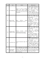
Page 56: ...rror code will be replaced by 060 014 Gas leakage testing Error 1 Gas leakage on solenoid valve of manual gas console Check the solenoid valve of manual gas console and confirm the connection is good and there is clean inside the valve 015 Gas leakage testing Error 2 Gas pressure between gas console solenoid valve HF box solenoid valve get down gas leakage in gas circuit and the displaying of gas ...

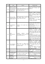
Page 57: ... or bad connections 9 Check if the IGBT of arc pilot is working normal 10 After connecting start signal check if there is open circuit voltage output 021 No transferred arc After making pilot arc current over 500ms there is still no current on work piece lead Means the current lower than 10A 1 Check if the initial position height is suitable 2 Check preflow gas and cutflow gas pressure value in co...

Page 58: ...l 042 N2 pressure too low When blow pipelines with N2 the N2 pressure lower than lower limiting value 1 When cutting current lower than 30A the lower limiting value is 5psi 2 When cutting current higher than 30A the lower limiting value is 30psi 1 Check the gas supply make sure the gas pressure enough 2 Check the gas console setting of pressure regulating valve according to the cutting chart 3 Run...

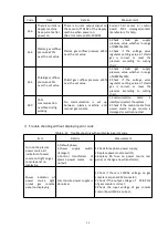
Page 59: ...rogram When finish cutting the start signal still not disconnected 2 Check if the cable from CNC to power source is damaged 053 Shield gas pressure too low Shield gas pressure lower than the lower limited value 2psi 1 Check the gas supply make sure the gas pressure enough 2 Check the gas console setting of pressure regulating valve according to the cutting chart 3 Run the gas leakage testing proce...

Page 60: ...t Deputy machine radiator temperature higher than 75 No error code on FLG 200HD 1 Check the radiator fan of plasma power source whether working normal 2 Open the machine use compressed air to blow away dust specially the dust on radiator and fan 3 If radiator temperature not high but appear warning on deputy machine shall check the temperature relay whether damage 071 Coolant over heat Coolant tem...

Page 61: ...h manual gas console after power on 1 Check the control cable connection between plasma power source socket X1 and gas console socket X10 make sure it s connected well and not damaged 2 The CAN communication circuit of control board PL01 for plasma power source and control board PL09 for manual gas console is broken contact manufacture for help 133 Gas console type not identified After power on pl...

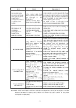
Page 62: ...o cutting chart 180 CAN communication overtime during working No communication is set up between plasma machine and manual gas console 1 Communication cable is interfered restart the system 2 Check if the control cable from power source to gas console is damaged or well connected 2 Trouble shooting without displaying error code Table 6 13 Trouble shooting without displaying error code Item Details...

Page 63: ... check the voltage of the 4 pressure sensors in gas console one by one adjust the corresponding pressure adjusting valve when displaying 50 on digital tube the output voltage of pressure sensor should be 2 38 0 2VDC 2 Check the cutting chart and make sure work piece under quality cutting thickness 3 Replace the consumables accordingly 4 Adjust the torch angle 5 Adjust the cutting speed according t...

Page 64: ...Three phase power supply of plasma power source lower 15 of rated input voltage this LED light on LED7 Three phase power supply of plasma power source higher 15 of rated input voltage this LED light on LED8 5V power indicator LED9 15V1 power indicator LED10 When pilot arc start this LED light on LED11 15V power indicator LED13 It is moving signal indicator after arc transferred this LED light on L...

Page 65: ...or LED3 5V power indicator Solenoid valve driving board AP3 PL11 Table 6 17 Manual gas console Solenoid valve driving board AP3 PL11 indicator Code Working Solenoid valve Code Working Solenoid valve LED1 YV1 YV2 LED17 YV17 YV18 LED3 YV3 YV4 LED19 YV19 LED5 YV5 YV6 LED20 YV20 LED7 YV7 YV8 LED21 YV21 YV22 LED9 YV9 YV10 LED23 YV23 YV24 LED11 YV11 YV12 LED25 YV25 YV26 LED13 YV13 YV14 LED27 YV27 YV28 L...

Page 66: ...e fused 3 Connect power again measure any two phase of the three phase inlet interface voltage any two phase voltage shall as same as power supply voltage If find problem here cut the main power and check the inlet wire circuit 4 Remove the top cover and two sides covers of the plasma power source 5 Check inside of the plasma power source for example if the PCB have color changes as burned or whet...

Page 67: ...ng time running without load 2 Coolant filer Note when remove coolant filter shell there maybe coolant flow out So before maintenance coolant filter discharge coolant first Check the coolant filter regularly Every 1 month or 50 arc hours when coolant system is working but cutting system not working open the drain valve of filter to discharge impurities NOTE use a hose to lead the coolant or load i...

Page 68: ... if coolant flow please firstly check if there is leakage on coolant pipes if no leakage start manual pump function to check the actual working coolant flow If coolant flow lower than 2 3L Min please refer to coolant filter maintenance chapter to make the first maintenance If still display code 060 after maintenance then check pump and motor If no problems on motor than make maintenance on pump Af...

Page 69: ... If digital tube pressure display increase then one or more inlet gas valve of gas console are not completely closed If gas supply valve pressure down but gas console digital tube display 0 or close to 0 then the gas supply pipelines between gas supply valve and gas console Gas leakage test mode 2 Press Knob 7 and select cutflow indicator light on Gas console inlet gas valve will be opened automat...

Page 70: ...d caused by overheat please replace it Check the contactor regularly check the connection is corrosive or not if the surface is black and hard please replace it 2 Cooling system Replace the coolant and clean the coolant pipelines regularly 6 month or 300 arc hours The maintenance time based on actual working strength and environment How to clean the coolant pipelines Step 1 Refer to coolant discha...

Page 71: ...e a gas leakage testing as gas leakage testing procedure Check all hoses make sure there is no twist damage and serious wearings Note if use the flammable gas the gas system maintenance must do everyday 4 HF box Open the HF box cover use compressed air to flow away the dust if any water clean it with cloth and find out the water source Check the HF ignition head to see if any corrosion Note Over c...

Page 72: ...le V102 V103 V202 V203 FF150R12RT4 8 IGBT module V9 GD75CUL120C1S 9 3 phase bridge rectifier V101 V201 MDS100 12 10 Temperature replay KT101 KT201 KSD305A 常闭 75 11 Liquid level switch BP1 F2HY K 1304075 12 Flow sensor BP2 RFO 155421 13 Temperature sensor RT1 RX WD 03 MF58 型热敏电阻 14 Power indicator HL1 AD16 22E g32 15 Solenoid valve YV1 2WT05010AT 16 Water pump Pump head MA1 101B070R12BA 200PSI 带滤网 ...

Page 73: ...iving board AP3 PL11 2 Manual gas console SQK B1 Table 7 3 Some parts of the gas console SQK B1 No Name Code Model 1 Pressure sensor SP1 SP2 SP3 SP4 PSE530 M5 2 Solenoid valve YV1 YV2 YV3 VX2C0ACH 3 Solenoid valve YV5 YV6 YV7 YV8 YV9 YV10 VX2A0ACH 4 Relief valve RP1 RP2 RP3 RP4 80 AR20 N02H NZ B 5 Main control board AP1 PL09 6 Control power divide board AP2 PL10 7 Solenoid valve driving board AP3 ...

Page 74: ...70 4 System wiring diagram Figure 7 1 System wiring diagram ...

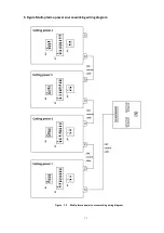
Page 75: ...71 5 Figure Multi plasma power source working wiring diagram Figure 7 2 Multi plasma power source working wiring diagram ...

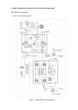
Page 76: ...72 6 Figure Complete plasma power source machine wiring diagram FLG 200HD wiring diagram 1 Main circuit wiring diagram 1 Figure 7 3 FLG 200HD Main circuit wiring diagram 1 ...

Page 77: ...73 2 Main circuit wiring diagram 2 Figure 7 4 FLG 200HD Main circuit wiring diagram 2 ...

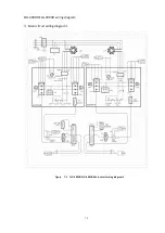
Page 78: ...74 FLG 300HD FLG 400HD wiring diagram 3 Main circuit wiring diagram 1 Figure 7 5 FLG 300HD FLG 400HD Main circuit wiring diagram 1 ...

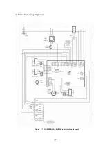
Page 79: ...75 4 Main circuit wiring diagram 2 Figure 7 6 FLG 300HD FLG 400HD Main circuit wiring diagram 2 ...

Page 80: ...76 5 Main circuit wiring diagram 3 Figure 7 7 FLG 300HD FLG 400HD Main circuit wiring diagram 3 ...

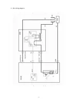
Page 81: ...77 6 HF striking diagram Figure 7 8 HF striking diagram ...

Page 82: ...erved to Westweld Huayuan Company If there is any changes in the user s manual forgive not to inform separately Westweld Ltd 4 23 4 No 51 Xuefu Avenue Nanan Chongqing China E mail info westweld com sales westweld com www westweld com ...

Reviews: