background image


Connection and Installation

Electric Connection 

ƒ

  Carefully place the solar module in its face or cover it in a suitable way to 

avoid short circuits during installing and connecting the panel. 

ƒ

  Now connect the consumers to the solar panel. The consumers must be able 

to sustain 21 V of direct current and consume no more than 2 W. Normally 
voltage or charge regulators are required between the solar module and the 
connected consumers to regulate the voltage directed to the consumer to the 
required input voltage. Please keep in mind that consumers directly con-
nected to the solar cell cannot work within their normal parameters on days 
with no or mediocre sunshine. For this reason solar modules are normally 
used to charge batteries which can provide the necessary power during over-
cast or rainy days. 

ƒ

  Open the cover of the connection box (4) by loosening the 4 screws. 

ƒ

  Use suitable cables according to the area in which the cell is mounted. You 

require at least two leads with a minimum cross section of 0.5 mm². Do not 
use the yellow and green lead, this is reserved for use as a grounding wire 
and may not be used for other applications. 

ƒ

  Strip the ends of the leads and use suitable press-on connectors. Use the 

proper tool to press the connectors on and cut excessively long cooper wire 
off or apply suitable insulation. 

ƒ

  Connect the connectors to the contact terminals and note the colours used for 

positive and negative current. 

ƒ

 Reattach 

the 

cover. 

Mounting 

ƒ

  Use the hinge on the top of the solar panel to mount it to a suitable wall. With 

the bracket on the rear you can set the angle of the solar panel after loosen-
ing the clamping screws. Use the included mounting clip to mount the bracket 
to the wall. For alignment please refer to the next chapter. 

ƒ

  You can also use the sheet metal mounting pieces and the sliding nuts to 

mount the panel to a solid surface. Dismount the bracket (black slotted 
screws) and dismount the sheet metal mounting pieces. Turn them to the 
outside and use the countersunk screws to attach the mounting pieces to the 
sliding nuts. 


Summary of Contents for 39 92 87

Page 1: ...Westfalia Bedienungsanleitung Nr 107192...

Page 2: ...Amorphes 2 W Solarmodul SL SM A 2 Artikel Nr 39 92 87 Amorphous 2 W Solar Module SL SM A 2 Article No 39 92 87 Bedienungsanleitung Instruction Manual...

Page 3: ...elp prevent misunderstandings and possible damage or injury Das Sonnenlicht steht Ihnen zum Nulltarif zur Verf gung ist nahezu uner sch pflich und Ressourcen schonend Die Nutzung der Photovoltaik erze...

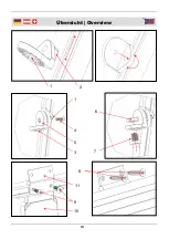
Page 4: ...III bersicht Overview 1 2 1 3 4 5 6 7 10 9 11 8...

Page 5: ...ng pieces 1 can be moved in the frame after twisting them by 90 By loosening the screws 4 from their nuts 5 you can tilt the angle pieces 3 The mounting bracket 7is secured with the nuts 6 in the angl...

Page 6: ...6 Mounting Page 6 Alignment Page 7 Maintenance and Care Page 7 Technical Data Page 8 Sicherheitshinweise Seite 2 Elektrischer Anschluss Seite 3 Montage Seite 3 Ausrichtung Seite 4 Wartung und Pflege S...

Page 7: ...direkt an einer Batterie Verwenden Sie z B einen passenden Laderegler zum Aufladen von Akkus Bei Verwendung des Moduls mit unserer Leuchtenserie SL X ist kein zus tzlicher Laderegler n tig An diese Le...

Page 8: ...estquerschnitt von 0 5 mm Verwenden Sie falls vorhanden nie die gelbgr ne Ader da diese f r Erdungszwecke reserviert ist und nicht f r andere Funktionen ver wendet werden darf Entmanteln Sie das Kabel...

Page 9: ...denn he sollte ein minimaler Abstand von 20 cm von der Modulunterkante zur angrenzenden Bepflanzung eingehalten wer den um eine Beschattung zu vermeiden Halten Sie einen Mindestabstand von 50 cm von d...

Page 10: ...ar module directly to a battery Use a suitable charge regulator to charge batteries If the module is connected to lamps from our SL X series no additional regulator is necessary the solar cell is conn...

Page 11: ...ell is mounted You require at least two leads with a minimum cross section of 0 5 mm Do not use the yellow and green lead this is reserved for use as a grounding wire and may not be used for other app...

Page 12: ...2 4 If the solar module is mounted close to the ground a minimum distance of 20 cm between the lower edge of the module and any plants to avoid shading out parts of the module Keep a minimum distance...

Page 13: ...mpp 114 mA Uoc 21 V Isc 190 mA Dimensions 315 x 240 x 20 mm L x W x D Weight 1 kg Bezeichnung Amorphes 2 W Solarmodul Typ Modell SL SM A 2 Pmpp 2 W Umpp 17 5 V Impp 114 mA Uoc 21 V Isc 190 mA Abmessun...

Page 14: ...V...

Page 15: ...then please keep in mind that many of its components consist of valuable materials which can be recycled Please do not discharge it in the rubbish bin but check with your local council for recycling f...

Reviews: