16
Receiver Instructions
Receiver Operation Way
1 Link: Charge the receiver then press and hold
'SET' button for 3 seconds,wait for the link
instruction after the orange light slowly flashes.
2 PM/W.BUS/PWM port modes select: Click and
hold the "SET" to charge, then enter into model
setting, slightly click the switcher mode, press and
hold to confirm.
R
eceiver connection and installation
Notice:pay attention to the positive and negative
polarity when connecting the power supply. Do not
use the power supply that exceeds the working
voltage of the receiver. Otherwise, the receiver will
be damaged!
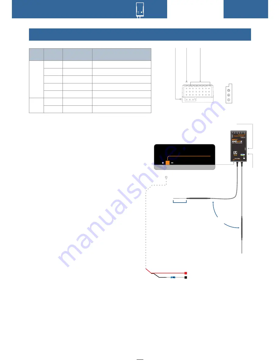
The RF209S is the latest series of high
performance receiver with 7 PWM channels, 1
PPM/W.BUS channel (User defined), and 1 W.BUS2
channel (User defined).
In order to obtain optimal signal retrieval
performance, the two antennas are preferably
processed 90° to each other when installed, as
shown in the bottom right diagram.
Notice:
1.If there is a metal conductor around the receiver
antenna,the signal performance would be affected.
In this case, the antenna should be bypassed by the
conductor, placed on both sides of the fuselage, and
it is better to make the antenna leak outside the
model casing ! In this way, good signal reception can
be maintained regardless of the flight attitude.
2. When the antenna is installed. The unshielded
end of the antenna should be as far away as
possible from the conductor materials such as metal
and carbon fiber. The antenna cable avoids bending
at large angles. And the end core should be as
straight as possible.
3. If the model body is covered with a conductive
material such as carbon fiber or metal, the antenna
portion must be extended beyond the body. At the
same time, do not stick too close to the conductive
Receiver LED STATUS LIST
Signal
Positive
Negtive
Mode
LED
Action
State
Work
Set
Blue
Green
Red
Orange
Red
Green
Blue
Never
Never
Never
Slow flash
Slow flash
Slow flash
Slow flash
W.BUS normal work mode
PWM normal work mode
No signal
Low voltage
Linking
W.BUS mode
PPM mode
USB port
90°
Ext
.
voltage
External voltage detection port
Antenna
Keep straight
The red is connected to
the positive pole
The resistance is connected to
the negative pole
1Ω resistance
Basic Operation
L
E
D
PPM/W
.BUS/W
.BUS2
CH1~7
:
PWM
PPM/W
.BUS
body after the antenna is extended. In addition, the
antenna should also be kept away from the fuel
tank.


