background image

2 6

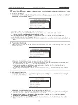
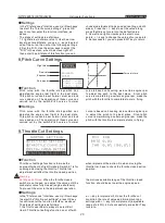
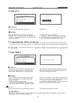
3.Code Match

Function

Settings

This remote control are the 2.4G spread 
spectrum, frequency hopping systems, with a high 
anti-interference. Each remote control only has an 

identification code information, before you use the 
remote control system pls matched with the 2.4G 
receiver which including in this device.

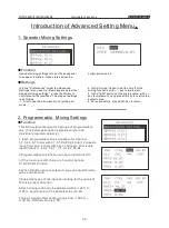
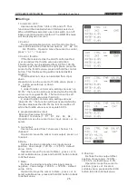
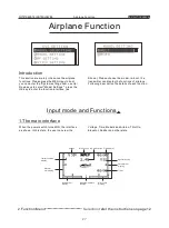
Enter the "Preferences" then select "Advanced 
settings" menu. Press OK key to enter the “Code 
“interface to select the "Advanced Settings" . As 
above. 
Specific settings following these steps: 
1. First to use the arrow keys to select the” code”, 

the process of the code needed within a short 
distance. 2.4G module system in the closed state is 
not available, please refer to "modulation type." 
Once the code successfully will initiative to return to 
the menu. also can press "exit” Key to Quit.

Warning 

When using this feature, please ensure that no 

operation of other remote control! 

Helicopter Functions

INSTRUCTION MANUAL 

WFT07 REMOTE CONTROL DEVICE

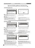
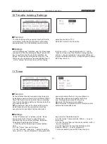
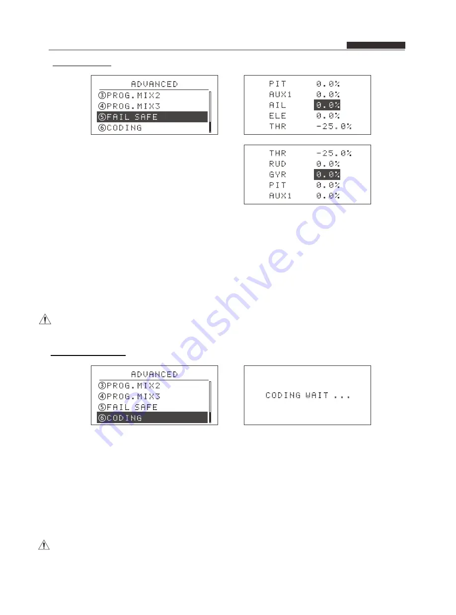
2.Fail Safe

Function

Settings

Fail safe function is used for various reasons 
(such as interference, long distance), when no 
transmitter signal of receiver, the receiver will 

automatically return to the default values position or 
maintain the current value .

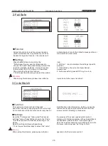
Press the MENU key to boot into the 
"Preferences" menu, use Up / Down keys to 
choose "Fail safe" and press OK key to enter the 
function interface, as above . Can not use this 
feature when the 2.4 G module in close state. 
The steps of settings is as follows:
1.First to use the arrow keys to select the edited 

item . 
2. With a + / - key to maintain the settings / specific 
position. 
3. Click OK key, the current actual channel 
parameters. 
4. Set successfully, press EXIT key to return.

Warning :

When using this feature, please ensure that no 

operation of other remote control!

Summary of Contents for WFT02

Page 1: ...V1 3 INSTRUCTION MANUAL www wflysz com Attention Please read the instruction before using the product Please keep this manual ON ON ON ON ON ...

Page 2: ...hout interfere 5 This RC equipment supports 3 groups of programmable mix 6 Can store 10 groups of model data 7 Functions design optimized operation convenience Service 1 The WFLY warranty the quality of science and technology within a year WFLY technology to bear the postage the user must provide a warranty card and proof of purchase Indispensable 2 Warranty card and proof of purchase effective by...

Page 3: ...of stick head Replacement throttle hand Helicopter Functions System Settings Input mode and Functions 1 Model parameters 2 Model Settings 3 Coaching Simulation 4 Control stick settings 5 Control stick Calibration 6 Restore factory settings 7 Tone settings 8 Contrast settings 9 Power supply scheme 10 Version information Preferences 1 Monitor 2 Dual Rate 3 Servo Reverse 4 End point 5 Sub trim 6 Trim...

Page 4: ...stick calibration 6 Restore factory settings 7 Tone settings 8 Contrast settings 9 Power supply scheme 10 Version information Preferences 1 Monitor 2 Dual Rate 3 Servo Reverse 4 End point 5 Sub trim 6 Trim settings 7 Flaperon mixing 8 Flap trim 9 Aileron diff control 10 Elev flap 11 Throttle curve settings 12 Throttle cut settings 13 Throttle holding settings 14 Timer 15 Advanced settings Advanced...

Page 5: ...trap 1 WFT07 remote control device 2 WFR07S 2 4Ghz receive 3 Simulator switch cable Manual 4 Transmitter 4cell battery case 6 WFLY neck strap WFT07 Remote control device contents WFT07 remote control device diagram INSTRUCTION MANUAL WFT07 REMOTE CONTROLDEVICE 5 Manual CD ROM 1 set 1 Root 1 This zhang 1 Only 1 A 1 Article ON ON ON ON ON ...

Page 6: ...trap attachment Aileron trim Left Up Right Down Menu Exit Add Reduce LCD OK K1 2 stalls Throttle holding and throttle cut K2 3 stalls Timer airplane 5channel and airplane Elev flap mixing K3 2 stalls Dual rate Fight mode normal special IDLE K4 Trainer 7channels WFT07 RC device parts of name INSTRUCTION MANUAL WFT07 REMOTE CONTROLDEVICE WFT07 RC device Positive Right hand throttle ...

Page 7: ...3 WFT07 RC device back WFT07 RC device parts of name Trainer DSC Handle Battery cover INSTRUCTION MANUAL WFT07 REMOTE CONTROLDEVICE ...

Page 8: ...8mm Frequency 2 400GHz 2 483GHz 1 AIL Aileron 2 ELE Elevator 3 THR Throttle 4 RUD Rudder 5 GRY Landing Gear Gyro 6 PIT Pitch 7 Auxiliary channel Channel 1 Channel 2 Channel 3 Channel 4 Channel 5 Channel 6 Channel 7 WFLY PCMS receiver can compatible with PCMS 4096 PCMS 1024 and PPM modulation Adaptive and have fail safe function ORGANIC 2 4G Note Any channel can be used as power input INSTRUCTION M...

Page 9: ...lect on the code the code process needs within a short distance 2 4G module system in the closed state is not available please refer to Once Code Coaching Simulation successfully will return to the menu Also can press exit button to return Warning When using this function please ensure that no other remote control operating 2 Receiver Settings Remote control device into this interface Then going r...

Page 10: ...Settings function enter Training simulation menu selected the trainer mode effect after re boot 3 Student machine setting Press MENU key of the another radio into the System Settings function entry Training simulation menu selected the Simulator Mode effect after re boot 4 Release Trainer switch K4 this time the student machine does not sending signal the operation completed by the trainer Advance...

Page 11: ...al with difficult moving actions Multiple mixing control system adjustable 9 point of the curve A variety of flight patterns ease flight 7 Note the special symbol For the safe use of this product pls pay attention to The marks have the following description of symbols Dangers If you use in without a proper operation it is possible to hurt user seriously injury or may even cause death If you use it...

Page 12: ...he item To enter the edit mode Press this button long time the selected item restore the default value 1 WFLY LOGO 2 2 4G RF circuit directed shown 2 4G under work closed without the logo 3 Aircraft models helicopter mode shows the helicopter LOGO airplane mode shows the airplane LOGO 4 Accumulative used time to display the cumulative duration of the using can also be reset clear 5 Battery voltage...

Page 13: ...o adjust the height you needed Adjust the height lower First make the top thread loose with the allen key then twist the stick head down then make the top head tighten with allen key the stick head was turned down Twist the top thread down from here the height of the stick head depends on the depth of the top thread Steps 1 Put the stick head on the stick 2 Put the top thread in the stick head wit...

Page 14: ...y of screw 3 and screw 4 to adjust the damp of throttle control felling Take the metal chip and screw down and put it on the similar position of the right side Take release link and spring Down and put it on the left side of the location of corresponding then twist bolt1 down until withstand the adjust nail in case adjust nsil will move away INSTRUCTION MANUAL WFT07 REMOTE CONTROLDEVICE Right hand...

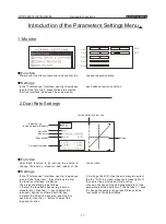
Page 15: ...unctions of the helicopter with the detailed description of each function Input mode and function introduction 1 The main interface When the power turned on the interface as shown In this state the user can view the machine voltage time display model type and aileron Throttle elevator rudder and so on trim state Voltage WFLY Logo RF modulation Time display Trainer function display Elevator trim di...

Page 16: ...e the arrow keys on the screen to select the functions you needed use up and down arrow keys to select function items With the left and right arrow keys to flip 2 In the functional state press OK key to enter sub menu of the function The function of specific configuration please refer the next chapter 3 When Settings finished press EXIT key to return to superior menu it will automatically store se...

Page 17: ... key into this function interface as shown above The steps of setting is as follows 1 Up Down keys to select the model 2 Click OK key to confirm 3 Settings finished press EXIT key to return to superior menu meanwhile it automatically store settings value 3 Coaching Simulation Normal normally use the model RF 2 4GHz work do not support the trainer Trainer mode use the unit as a trainer use the trai...

Page 18: ...e MENU key to boot into the System Settings menu use Up Down keys to select Stick calibration and press OK key to enter the function interface as Shown above Specific settings follow these steps 1 First to use the arrow keys to select the edited item aileron calibration as example 2 Put the calibrate joystick placed in the midpoint of the channel position options Up Down key implement the control ...

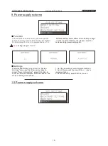
Page 19: ...t into the System Settings menu use Up Down keys to select Sound press the OK key to enter the function interface as above The steps of settings is as follows 1 Into the items press OK key to select the sound on or off 2 Automatically saved after confirmation 8 Contrast Settings Function Settings The contrast setting function can adjust the brightness of the display increase or decrease the contra...

Page 20: ...sponding power supply plan Press the MENU key to boot into the System Settings menu use Up Down arrow keys to select Power Information press OK button to enter the function interface As shown above The steps of setting is as follows 1 Use the arrow keys to edit the selected item 2 Select the power scheme with the key to implementation 3 Set successfully press EXIT key to exit 10 Power supply schem...

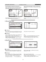
Page 21: ... steps of settings is as follows 1 Select the required channel eg aileron elevator etc Use the key to select the required channel confirmed with OK key 2 Select the K3 switch position position 0 or position 2 Use the button to select the required location 3 Settings the D R Use the arrow keys to select the the D R in screen when the screen light off then enter the edit mode of this function You ca...

Page 22: ... key to confirm enter the function interface As above The steps of settings is as follows 1 First to use the arrow keys to select the edited item 2 with keys to switch the action is normal or reverse and use the OK keys to implement 3 Set successfully press EXIT key to return 4 End Point Function Settings End point function can determine the end point of the servo s initial value adjust the larges...

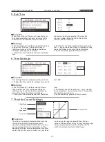
Page 23: ...trim press the OK key to confirm you access in this interface as above The steps of settings is as follows 1 First to use the arrow keys to select the edited item 2 Set the amount of the sub trim of movement with the keys or used the OK key to implement long press the OK kay can restore the default value 3 Set successfully press EXIT key to return 6 Trim Settings Function Settings Trim settings fu...

Page 24: ...ed the engine rpm flight in the best state This pitch curve can be set normal stunt and lock curve and so on The operation of those curve can carried out by the switch Pitch curve of normal curve is based on hovering as a certain engine rpm to adjust the pitch to the best place Stunt pitch curve is maintaining a certain engine rpm make the pitch with the throttle to complete stunts in flying 9 Thr...

Page 25: ...u in warning tone to land the plane safely on the ground before you used up the fuel The maximum time of the timer is 99 minutes and 59 seconds during operation timer tips every1minute countdown to 2seconds each second prompt with short ring countdown to 10seconds each second prompt with long ring Timing end prompt with long ring can set the timing and countdown Control way K2 switch control throt...

Page 26: ...swash type selection press OK key to enter with key to implement the selection mode 3 Set successfully press EXIT key to return Swash Parameter adjustment Function Settings Swash parameter adjustment function is works for adapting the aileron elevator pitch three parts In the Preferences interface use Up Down keys to select the Swash press OK key to confirm enter the Swash type Adjustment interfac...

Page 27: ...ptions use key to implement the function Long press OK key to restore default 4 In the position option to set the control position on or off this function with a key to implement 5 In the ratio option set the mixing value with key to implement Long press OK key to restore the default value 4 Set successfully press EXIT key to return 14 Advanced Settings Function Settings In order to make aircraft ...

Page 28: ...uccessfully press EXIT key to return Helicopter Functions INSTRUCTION MANUAL WFT07 REMOTE CONTROLDEVICE This RC equipment supports 3 groups of programmable mix The below description explains only for one individual programmable mix 1 Each programmable mix is available for Channel 1 2 3 4 5 6 7 to mix with V1 K1 K2 K3 K4 total 12 mixable input You can mix them with any 7 channels 12 mixable input C...

Page 29: ...ile the throttle value less than 50 0 2 under throttle control mode setting value as down 50 0 the function will be activated while the throttle value less than 50 0 the function will be off while the throttle value over or equals 50 0 4 programmable mix input Mix input has below 12 options channel 1 to channel 7 V1 K1 K2 K3 K4 Operation move the cursor to mix input press or to select 5 mix output...

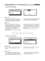
Page 30: ...xit Key to Quit Warning When using this feature please ensure that no operation of other remote control Helicopter Functions INSTRUCTION MANUAL WFT07 REMOTE CONTROLDEVICE 2 Fail Safe Function Settings Fail safe function is used for various reasons such as interference long distance when no transmitter signal of receiver the receiver will automatically return to the default values position or maint...

Page 31: ...se Up Down keys to select Model Settings press the OK key to enter the function interface as Shown Please choose the model re boot the transmitter can display the functions of airplane Following description the details of each function Input mode and Functions 1 The main interface When the power switch turned ON the interface as shown In this state the user can view the Voltage Time Models and Ail...

Page 32: ...ted the options press the key to edit the data Long press OK key to restore the default values 3 Set successfully press EXIT key to retrun Introduction of System Settings Menu Introduction of Parameter Settings Menu 1 Model parameters 2 Model Setting 3 Coaching Simulation 4 Stick settings 5 Stick calibration 6 Restore factory settings 7 Tone settings 8 Contrast settings 9 Power supply scheme 10 Ve...

Page 33: ...l press OK key to enter the function interface as above The step of settings is as follows 1 Use the up down key to select the Edit Item 2 Selected the options press the key to edit the data Long press OK kry to restore the default value 3 Set successfully press EXIT key to return 10 Ele Flap Mixing Function Settings This feature is to make the flap elevator doing the corresponding action Flap dow...

Page 34: ...the Preference Settings then select the Advanced Settings menu use up down keys to select the Elevator mixing press OK key to enter the function interface as above The step of settings is as follows 1 Using the up down keys to choose the edit item 2 Selected the options press the key to edit the data Long press OK key to restore the default values 2 Set successfully press EXIT to return 11 Throttl...

Page 35: ...edit item 2 Selected the options press the key to edit the data Long press OK key to restore the default values 4 Set successfully press EXIT key to return 3 V Tail Mixing Function Settings This feature is use for V tail aircraft with elevator and rudder mixing function Enter the Preferences Settings then select Advanced Settings menu use Up Down keys to select V tail mixing and press OK key to en...

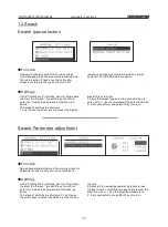
Page 36: ...vice Enter the Preference Settings under code menu Click OK key to enter the state of the coding As above The step of settings is as follows 1 First to use the arrow keys to select on the code the process of the code operation needed within a short distance 2 4G module system can not use this function in the closed state please refer to Once the code Coaching Simulation successfully systemwill ini...

Page 37: ...WFLY TECHNOLOGY DEVELOPMENT CO LTD Address C2 Building 4th Floor Xiang Li Industrial Park He Ping Hao Ye Road Fuyong Street Bao an District Shenzhen Tel 86 755 26621859 E mail info wflysz com Web www wflysz com ...

Reviews: