background image

18 

Assembly Instructions 


Tools required (not provided): Phillips screwdriver, stud finder, tape measure, pencil, power drill and 1/8’’ drill bit. 


38.


Ask for assistance to position the assemble fireplace at the desired location against a wall. If necessary, 
adjust the pre-attached Floor Levelers at the bottom of the Base Front Molding (K) to correct the tilting 
and level the doors. 

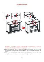
39.


Now, follow the instructions printed on the plastic bag containing the Tipping Restraint Hardware to 
attach the tip-over restraints to the unit and the wall. 

NOTE:


The  tipping  restraint  hardware  included  is  for  wooden  stud  wall  construction.  It  must  be 

attached  to  a  wall  stud.  Depending  upon  your  wall  construction,  different  anchor  hardware  maybe 
required.  Please  contact  your  local  hardware  store  for  assistance.  Young  children  can  be  seriously 
injured by tipping furniture. You must install the tipping restraint hardware with the unit to prevent the 
unit  from  tipping,  causing  any  accidents  or  damage.  The  tipping  restraints  are  intended  only  as  a 
deterrent, they are not a substitute for proper adult supervision. The tipping restraints are not earthquake 
restraints. If you wish to add the extra security of earthquake restraints, they must be purchased and 
installed separately

.


40.


Connect the fireplace to the power transformer. Follow the operating manual for the electric fireplace 
insert to control your fireplace. 

WARNING 

Serious or fatal crushing injuries can occur from furniture 
tip-over. To help prevent tip-over: 


Install tip-over restraint provided. 


Place heaviest items in the lowest drawers. 


Do not set TV’s or other heavy objects on top of this product, unless 
the product is specifically designed to accommodate them. 


Never allow children to climb or hang on drawers, doors, or shelves. 


Never open more than one drawer at a time. 


Use of tip-over restraints may only reduce, but not eliminate, the 
risk of tip-over. 

Summary of Contents for 6415117

Page 1: ...ts are missing DO NOT return this item to the store where it was purchased Please call our toll free customer service number and have your instructions and parts list ready to provide the model name p...

Page 2: ...t goes into the pre drilled hole at the end of the panel with the Cam Lock 2 Insert the Cam Lock into the pre drilled large hole in the panel Make sure the arrow on the Cam Lock is pointed towards the...

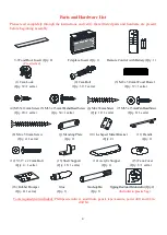
Page 3: ...l Qty 1 E Right Side Panel Qty 1 F Left Partition Panel Qty 1 G Right Partition Panel Qty 1 H Middle Crossbar Qty 1 I Middle Left Stile Qty 1 J Middle Right Stile Qty 1 K Base Front Molding Qty 1 L Ba...

Page 4: ...mmWasherHeadScrew 6 M4x38mmScrew 7 M3 5x15mmPanHeadScrew Qty 20 1 extra Qty 34 1 extra Qty 12 1 extra Qty 8 1 extra 8 M4 x 50 mm Screw 9 Mending Plate 10 L shaped Metal Bracket 11 Handle Qty 4 1 extra...

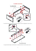
Page 5: ...s on the Fixed Shelf B Bottom Panel C and Partition Panels F and G with a Phillips screwdriver NOTE Screw in cam bolts must be screwed down flush 3 Insert two Wood Dowels 3 into the inner holes on the...

Page 6: ...e Middle Crossbar H to the Fixed Shelf B by engaging three Cam Locks 1 Refer to page 2 on Cam Lock system operation supplement 5 Align and attach the Middle Left Stile I to the Left Partition Panel F...

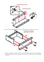
Page 7: ...ing two Cam Locks 1 7 Glue the Wood Dowels 3 into the inner holes of Fixed Shelf B Bottom Panel C Partition Panels F and G Base Front Stretcher L and Base Rear Stretcher M as shown NOTE Do Not Insert...

Page 8: ...tructions 8 Attach the Fixed Shelf B beween the Partition Panels F and G by engaging four Cam Locks 1 9 Align and attach the Base Front Stretcher L to the Bottom Panel C with four Cam Locks 1 F G B 1...

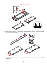
Page 9: ...Bottom Panel C with three Cam Locks 1 11 Using the wood dowels as a guide firmly press the assembled Partition Panels F and G to the Bottom Panel C and fasten them in place with four 50 mm Screws 8 Fu...

Page 10: ...olts 2 into the designated small holes on the Top Panel A and Side Panels D and E with a Phillips screwdriver 13 Glue the Wood Dowels 3 into the inner holes on both Side Panels D and E and the Base Fr...

Page 11: ...on the assembled base Firmly press them together and fasten it in place by engaging three Cam Locks 1 15 Repeat the same procedure to attach the Right Side Panel E at the other end 16 Fasten the Base...

Page 12: ...the Base Front Molding K to the Base Front Stretcher L by using eight 38 mm Screws 6 18 Place the Top Panel A onto the inserted Wood Dowels 3 properly and fasten it in place by engaging eight Cam Loc...

Page 13: ...ht and there are no gaps between the parts This will help keep the unit square 22 Pick up the Middle Back Panel Q and align the pre drilled holes against the upper long edge with the pilot holes on th...

Page 14: ...ht Side Panel E Please follow the steps below to combine the door hinges together a Extend both hinge arms of the Door P to open position b Locate the lugs on the mounting plates pre attached on the R...

Page 15: ...interchange with the Door Glass Insert T or Mesh Trims U depending on your configuration 30 To change the configuration loosen the screws on the inside of Doors P and rotate the clips to remove the d...

Page 16: ...enter it in the opening DO NOT drag the insert across the Bottom Panel C as it may scratch the unit 34 Use the pilot holes as a guide fasten two L shaped Metal Brackets 10 onto the Firebox Support O w...

Page 17: ...he paper backing from the Acrylic Stopper 14 then properly align the acrylic stopper into the cut out on the acrylic stopper template on the Top Panel A Press down on the acrylic stopper to help adhes...

Page 18: ...e You must install the tipping restraint hardware with the unit to prevent the unit from tipping causing any accidents or damage The tipping restraints are intended only as a deterrent they are not a...

Page 19: ...on the furnishing may encourage a child to climb on the furnishing and as a result may tip over onto the child NEVER allow children to climb or play with the TV or furnishing supporting the TV NEVER...

Page 20: ...a m 4 30 p m PST Monday to Friday www whalenfurniture com MAXIMUM RECOMMENDE D WE IGHT LOADS PLACE TV BEHIND THE STOPPER FITS UP TO MOST 152 4 cm 60 in DIAGONAL FLAT PANEL TVS MAXIMUM LOAD 61 2 KG 135...

Reviews: