background image

5


Assembly Instructions 


4.


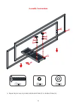
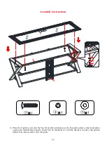
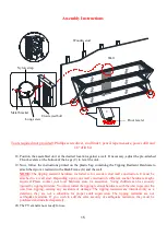
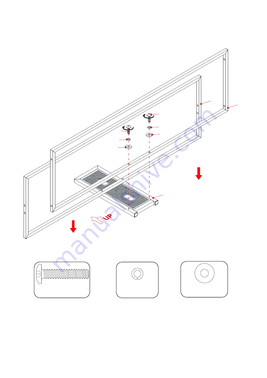
Repeat the previous step to fasten the Bottom Frame (F) to the Back Frame (G).


×

2


×

2


×

2


G

1

1

5

4

5

4

F

E

Summary of Contents for 6420344

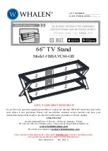
Page 1: ... NOT return this item to the store where it was purchased Please call our toll free customer service number and have your instructions and parts list ready to provide the model name part name or factory number 1 866 942 5362 Pacific Standard Time 8 30 a m 4 30 p m Monday Friday Or visit our web site 24 hours a day 7 days a week for product assistance at www whalenfurniture com Or e mail your reque...

Page 2: ...of the unit due to small tremors bumps or climbing The restraint is only a deterrent and is not a substitute for proper adult supervision Use of tip over restraints may only reduce but not eliminate the risk of tip over MAXIMUM LOAD 22 7 kg 50 lb FITS UP TO MOST 203 2 cm 80 DIAGONAL FLAT PANEL TVs MAXIMUM LOAD 61 2 kg 135 lb THIS UNIT IS NOT INTENDED FOR USE WITH CRT TVS USE ONLY WITH FLAT PANEL T...

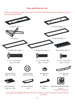
Page 3: ...ty 1 G Back Frame Qty 1 1 1 4 x 38 mm Bolt 2 1 4 x 28 mm Bolt 3 1 4 x 15 mm Bolt Qty 18 1 extra Qty 4 1 extra Qty 2 1 extra 4 Lock Washer 5 Flat Washer 6 Glass Riser 7 Velcro Strip Qty 22 1 extra Qty 22 1 extra Qty 4 Qty 2 8 Glass Bumper 9 Acrylic Stopper Hex Wrench Tipping Restraint Hardware Kit Qty 16 1 extra Qty 1 Qty 1 Qty 1 Included in Plastic Bag Tools required not included Phillips screwdri...

Page 4: ...ghten all bolts This will make the assembly easier 1 Unpack the unit and confirm that you have all the hardware and required parts 2 Locate the Back Frame G on a level and protective surface with the flush surface facing up 3 Fasten the Middle Frame E to the Back Frame G with two 38 mm Bolts 1 and four Washers 4 and 5 2 2 2 5 4 1 1 5 4 E G ...

Page 5: ...5 Assembly Instructions 4 Repeat the previous step to fasten the Bottom Frame F to the Back Frame G 2 2 2 G 1 1 5 4 5 4 F E ...

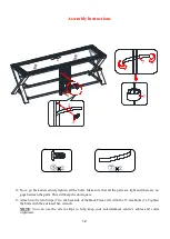
Page 6: ...6 Assembly Instructions 5 Align and attach one Leg C to the Middle Frame E and Bottom Frame F with four 38 mm Bolts 1 and eight Washers 4 and 5 as shown 4 4 4 G F E 1 4 5 C ...

Page 7: ...7 Assembly Instructions 6 Fasten the Top Frame D to the Leg C with two 38 mm Bolts 1 and four Washers 4 and 5 as shown 2 2 2 The threaded sockets for risers on the opposite side D F E C 1 4 5 ...

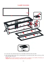
Page 8: ...8 Assembly Instructions 7 Attach the other Leg C to the Shelf Frames D E and F with six 38 mm Bolts 1 and twelve Washers 4 and 5 6 6 6 C D F E C 5 4 1 ...

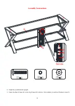
Page 9: ...9 Assembly Instructions 8 Stand the assembled unit upright 9 Fasten the Back Frame G to the Top Frame D with two 38 mm Bolts 1 and four Washers 4 and 5 2 2 2 G D C C 1 4 5 ...

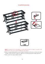
Page 10: ...10 Assembly Instructions 10 Securely screw four Glass Risers 6 into the drilled holes on the Top Frame D as shown 4 D 6 C C ...

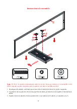
Page 11: ...ass A onto the Top Frame D and make sure the threaded sockets on the metal plates overlap the drilled holes properly Insert four 28 mm Bolts 2 with the Washers 4 and 5 through the drilled holes and securely screw into place 4 4 4 C C D G A 2 4 5 ...

Page 12: ...re are no gaps between the parts This will keep the unit square 13 Attach two Velcro Strips 7 to the backside of the Back Frame G with the 15 mm Bolts 3 Tighten the bolts with the enclosed hex wrench NOTE You can use the velcro strips to help keep your entertainment center s cables and cords organized 2 2 A C C 3 7 G 7 7 ...

Page 13: ...ce the Glass Shelves B onto the Glass Bumpers 8 and push the glass shelves all the way back against the Back Frame G NOTE Make sure that the glass sits correctly If glass is scratched you can minimize the damage by using a BLACK marker and filling in scratched area from underneath 16 E F C C A B B 8 E F E F B 8 ...

Page 14: ...el television on the top of your stand Otherwise skip to Step 17 16 Remove the paper backing from the Acrylic Stopper 9 and place it in the cut out of the acrylic stopper template on the front of the Top Glass A Make sure it is properly aligned before applying pressure 17 Remove the acrylic stopper template carefully 1 A A A ...

Page 15: ...It must be attached to a wall stud Depending upon your wall construction different anchor hardware maybe required Please contact your local hardware store for assistance Young children can be seriously injured by tipping furniture You must install the tipping restraint hardware with the unit to prevent the unit from tipping causing any accidents or damage The tipping restraints are intended only a...

Page 16: ...e Care It is best to keep your furniture in a climate controlled environment Continual exposure to damp and wet environment can cause corrosion It is advised to keep furniture away from direct sunlight as it may damage the finish Indoor furniture is not recommended for outdoor use Proper care and cleaning at home will extend the life of your purchase Following these important and helpful tips will...

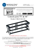
Page 17: ...producto a la tienda donde lo compró Por favor llame a nuestro departamento de ayuda al cliente teniendo su instructivo y lista de partes para proveer el modelo nombre de parte o el número de fábrica 1 866 942 5362 Hora estándar del Pacífico 8 30 a m 4 30 p m Lunes Viernes O nuestra página de Internet 24hrs al día 7 días a la semana para asistencia en el producto www whalenfurniture com O mande su...

Page 18: ...a causa de pequeños temblores golpes El tope de movimiento es solo un impedimento no hay substituto para la supervisión adulta El uso del tope de movimiento puede reducir pero no eliminar el riesgo de voltearse la unidad CARGA MÁXIMA 22 7 kg 50 lb PARA TVs DE PANTALLA PLANA DE HASTA 203 2 cm 80 EN DIAGONAL CARGA MÁXIMA 61 2 kg 135 lb PONER LA TV DETRÁS DEL TOPE ESTA UNIDAD NO DEBE UTILIZARSE CON T...

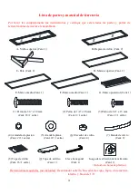
Page 19: ...sterior Cant 1 1 Perno de 1 4 x 38 mm 2 Perno de 1 4 x 28 mm 3 Perno de 1 4 x 15 mm Cant 18 1 extra Cant 4 1 extra Cant 2 1 extra 4 Arandela de presión 5 Arandela plana 6 Elevador de vidrio 7 Banda de velcro Cant 22 1 extra Cant 22 1 extra Cant 4 Cant 2 8 Tope de vidrio 9 Tope de acrílico Llave hexagonal Juego de restricción de movimiento Cant 16 1 extra Cant 1 Cant 1 Cant 1 Incluido en bolsa de p...

Page 20: ... los pernos esto hará el ensamble más fácil 1 Desempacar la unidad y confirmar que se tiene todo el material de ferretería y partes requeridas 2 Localizar el marco posterior G en una superficie nivelada y protectora con la superficie nivelada hacia arriba 3 Sujetar el marco medio E al marco posterior G con 2 pernos de 38 mm 1 y 4 arandelas 4 y 5 2 2 2 1 5 4 E G 5 4 1 ...

Page 21: ...5 Instrucciones de ensamble 4 Repetir el paso previo para sujetar el marco inferior F al marco posterior G 2 2 2 G 1 1 5 4 5 4 F E ...

Page 22: ...6 Instrucciones de ensamble 5 Alinear y adjuntar una pata C al marco medio E y al marco inferior F con 4 pernos de 38 mm 1 y 8 arandelas 4 y 5 como se muestra 4 4 4 G F E 1 4 5 C ...

Page 23: ...C 1 4 5 Instrucciones de ensamble 6 Sujetar el Marco superior D a la pata C con 2 pernos de 38 mm 1 y 4 arandelas 4 y 5 como se muestra 2 2 2 Los insertos roscados para los niveladores están en el lado opuesto ...

Page 24: ...8 Instrucciones de ensamble 7 Adjuntar la otra pata C a los marcos de las repisas D E y F con 6 pernos de 38 mm 1 y con 12 arandelas 4 y 5 6 6 6 C D F E C 5 4 1 ...

Page 25: ...9 Instrucciones de ensamble 8 Poner la unidad ensamblada en posición vertical 9 Sujetar el marco posterior G al marco superior D con 2 pernos de 38 mm 1 y 4 arandelas 4 y 5 2 2 2 G D C C 1 4 5 ...

Page 26: ...10 Instrucciones de ensamble 10 Atornillar 4 elevadores de vidrio 6 en los agujeros perforados en el marco superior D como se muestra 4 D 6 C C ...

Page 27: ...A sobre el marco superior D y asegurar que los espacios roscados en las placas de metal sobrepasan los agujeros perforados Insertar 4 pernos de 28 mm 2 con las arandelas 4 y 5 a través de los agujeros perforados y atornillar en su lugar 4 4 4 C C D G A 2 4 5 ...

Page 28: ... las partes Esto ayudara a mantener la unidad cuadrada 13 Adjuntar 2 bandas de velcro 7 a la parte posterior del marco posterior G con los pernos de 15 mm 3 Apretar los pernos con la llave hexagonal provista NOTA Usted puede usar las bandas de velcro para ayudar a mantener los cables de su centro de entretenimiento organizados 2 2 A C C 3 7 G 7 7 ...

Page 29: ... las repisas de vidrio B sobre los topes de vidrio 8 y empujar las repisas de vidrio todo el camino en contra del marco posterior G NOTA Asegurar que el vidrio esté sentado correctamente Si el vidrio se raya usted puede minimizar el daño usando un marcador NEGRO y llenado el área rayada por abajo 16 E F C C A B B 8 E F E F B 8 ...

Page 30: ...ón de pantalla plana directamente sobre la consola De otra manera vaya al paso 17 16 Retirar el papel del tope de acrílico 9 y poner en el recorte del templado del tope de acrílico en la parte frontal del vidrio superior A Asegurar que este alineado antes de aplicar presión 17 Retirar el temple del tope de acrílico 1 A A A ...

Page 31: ...ed con vigas de madera Se debe sujetar a un barrote de pared Dependiendo de la construcción de su pared es posible que se requiera ferretería diferente Póngase en contacto con su ferretería local para obtener ayuda Niños pequeños pueden resultar lastimados por muebles inclinados Debe instalar el juego de restricción de movimiento con la unidad en función para prevenir la inclinación de la unidad c...

Page 32: ... Es mejor mantener la unidad en un área de clima controlado La exposición continua a lugares húmedos y mojados puede causar corrosión Es recomendable mantener la unidad lejos del sol directo ya que puede dañar el acabado Los muebles de interior no están recomendados para uso exterior Cuidados adecuados y limpieza pueden extender la vida útil de su unidad Siga estas recomendaciones y mantendrá su m...

Reviews: