background image

                    IF YOU NEED TO 

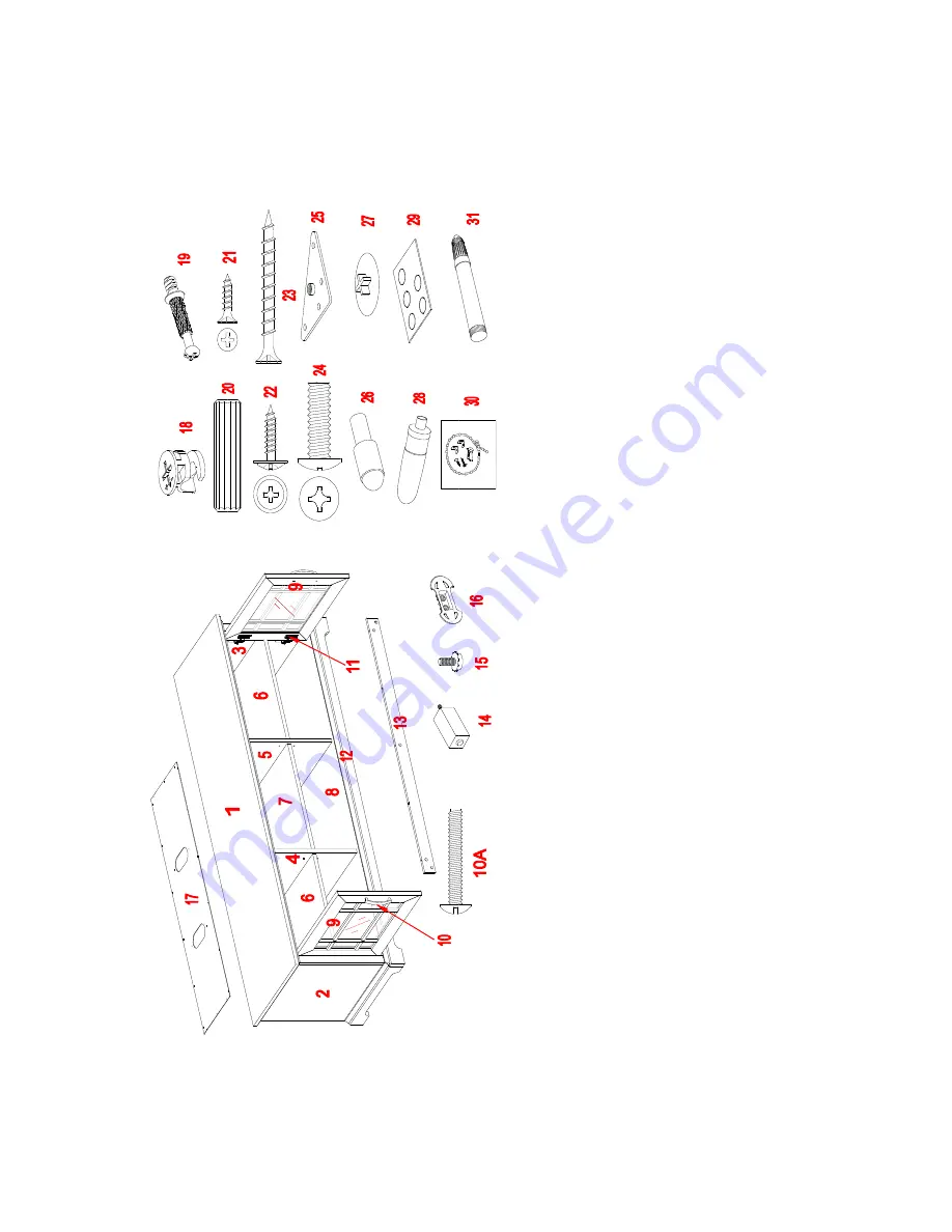
ORDER ANY REPLACEMENT PARTS, PLEASE USE THE LIST BELOW

                             TV Co

n

so

le (AVCLEC6

0

-DB)

*

A

V

C

L

E

C

60-

D

B

-1

-T

P

T

op Pan

el

*

A

V

C

L

EC

60-

D

B

-17-

BP

B

ack

 P

an

el

*

A

V

C

L

E

C

60-

D

B

-2

-L

S

F

L

ef

t S

ide F

ram

e

*

A

V

C

L

EC

60-

D

B

-18-

C

L

C

am

 L

o

ck


*

A

V

C

L

E

C

60-

D

B

-3

-R

S

F

R

ig

h

t S

ide F

ram

e

*

A

V

C

L

EC

60-

D

B

-19-

C

B

C

am

 Bol

*

A

VC

L

E

C

60-

DB

-4

-L

P

P

L

ef

t P

artition

 P

an

el 

*

A

VC

L

E

C

60-

DB

-20-

M8x

30W

D

M

8 x

 30 m

m

 W

ood Dow

el    

*

A

VCL

E

C6

0

-DB

-5

-R

P

P

Rig

h

t P

artitio

n

 P

an

el 

*

A

VCL

E

C6

0

-DB

-2

1

-M3

x

1

2

S

M3

 x

 1

2

 m

m

 Screw

*

A

VC

L

E

C

6

0

-DB

-6

-S

A

S

Sm

all A

d

ju

stab

le Sh

elf


*

A

V

C

L

E

C

60-

D

B

-22-

M3.5x

16WH

S

M3.5 x

 16 m

m

 Was

h

er H

ead S

crew


*

A

VC

L

E

C

6

0

-DB

-7

-L

A

S

L

arg

e A

d

ju

st

able Sh

elf


*

A

V

C

L

E

C

60-

D

B

-23-

M4x

40WS

M

4 x

 40 m

m

 Wood

 S

cr

ew

*

A

VC

L

E

C

6

0

-DB

-8

-B

P

B

o

tto

m

 P

an

el

*

A

V

C

L

E

C

60-

D

B

-24-

3/

4B

Ø

1

/4

" x

 3/

4” Bol

t

*

A

VC

L

E

C

6

0

-DB

-9

-D

D

oor

*

A

V

C

L

E

C

60-

D

B

-25-

MB

Metal B

rack

et   

*

A

V

C

L

E

C

60-

D

B

-10-

H

H

an

dl

e    

*

A

V

C

L

E

C

60-

D

B

-26-

S

P

Shelf

 P

in 

*

A

V

C

L

E

C

60-

D

B

-10A

-H

B

H

an

dl

e Bol

t       

*

A

V

C

L

E

C

60-

D

B

-27-

C

L

C

Ca

m

 Lo

ck

 Co

ve

r

*

A

V

C

L

E

C

60-

D

B

-11-

D

H

S

D

oor H

in

g

e w

it

h

 S

crew

s

*

A

V

C

L

E

C

60-

D

B

-28-

G

Glu

e

*

A

V

C

L

E

C

60-

D

B

-12-

BF

M

B

o

tto

m

 Fro

n

t Mo

ld

in

g

*

A

V

C

L

E

C

60-

D

B

-29-

R

P

R

u

bber Pad

*

A

V

C

L

E

C

60-

D

B

-13-

BBS

B

o

tto

m

 B

ack

 Stretch

er

*

A

VC

L

E

C

6

0

-DB

-3

0

-T

R

HK

T

ip

p

in

g

 R

estrain

t Hard

w

are Kit

*

A

V

C

L

E

C

60-

D

B

-14-

C

S

L

C

en

ter S

u

pport

 w

/L

ev

el

er 

*

A

V

C

L

E

C

60-

D

B

-31-

T

U

P

T

o

uc

h-up

 P

en

*

A

V

C

L

E

C

60-

D

B

-15-

F

L

F

loor L

ev

el

er    

*

A

V

C

L

E

C

60-

D

B

-C

H

C

om

pl

et

e H

ardw

are

*

A

V

C

L

E

C

60-

D

B

-16-

C

W

C

able W

h

eel 

Summary of Contents for AVCLEC60-DB

Page 1: ...mbly or if parts are missing DO NOT return this item to the store where it was purchased Please call our toll free customer service number and have your instructions and parts list ready to provide th...

Page 2: ...O ADJUST DOOR UP OR DOWN MAXIMUM RECOMMENDED WEIGHT LOADS MAXIMUM LOAD 50 lb 22 6 kg FITS UP TO MOST 70 FLAT PANEL TVs MAXIMUM LOAD 135 lb 61 2 kg THIS UNIT IS NOT INTENDED FOR USE WITH CRT TVS USE ON...

Page 3: ...ping lightly with a rubber mallet IF NECESSARY CAM LOCK SYSTEM OPERATION HOW THE KNOCK DOWN KD ASSEMBLY SYSTEM WORKS 1 Screw the Cam Bolt into the threaded inserts on the panel Connect both panels tog...

Page 4: ...instructions and verify that all listed parts and hardware are present before beginning assembly A Top Panel 1 B Left Side Frame 1 C Right Side Frame 1 D Left Partition Panel 1 E Right Partition Pane...

Page 5: ...Lock 2 Cam Bolt 3 M8 x 30 mm Wood Dowel 20 1 extra 20 1 extra 22 1 extra 4 M3 x 12 mm Screw 5 M3 5 x 16 mm Washer Head Screw 6 M4 x 40 mm Wood Screw 8 1 extra 22 1 extra 4 1 extra 7 Handle 8 Handle B...

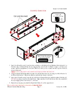
Page 6: ...the hardware and required parts Assembly the unit on a carpeted floor or the empty carton to avoid any scratch 2 Securely screw the Cam Bolts 2 into the designated small holes on the Top Panel A Left...

Page 7: ...ery important to use a small mount of glue on both ends of dowels 4 Align and attach the Bottom Back Stretcher I to the Bottom Panel G by using two Wood Dowels 3 and three Cam Locks 1 Make sure that t...

Page 8: ...f each Partition Panel D and E and fasten them to the Bottom Panel G with four M4 x 40 mm Wood Screws 6 as shown Make sure the threaded inserts for Cable Wheel on the Partition Panels D and E face the...

Page 9: ...els 3 into the inner holes on the top edge of Side Frames B and C and the Partition Panels D and E As shown 9 Position the Top Panel A onto the inserted Wood Dowel 3 making the back egdes are even wit...

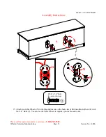
Page 10: ...Metal Brackets 10 to connect the Bottom Front Molding H with both Side Frames B and C using four M3 x 12 mm Screws 4 per bracket As shown 11 Tightly screw the Central Support M into the threaded inse...

Page 11: ...62 Whalen Furniture Manufacturing Page 11 Factory No 16086 Assembly Instructions 12 Securely screw the Floor Levelers 11 into the threaded holes on the Metal Brackets 10 and set the Floor Levelers 11...

Page 12: ...aps between the pieces This will help keep the unit square 14 Using the pilot holes as a guide align and attach the Back Panel L to the assembled unit by using twenty two 16 mm Washer Head Screws 5 th...

Page 13: ...iture Manufacturing Page 13 Factory No 16086 Assembly Instructions 15 Attach two Cable Wheels N to the threaded inserts on the back side of Partition Panels D and E with four 3 4 Bolts 9 You can use t...

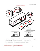
Page 14: ...he sides of each compartment Make sure you place the four Shelf Pins in the same level so the shelf is not tilted Tilt and set the Adjustable Shelves J and K onto the Shelf Pins 12 with the finished e...

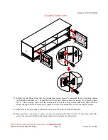
Page 15: ...Base for an easy fit Align and insert the U slot on Hinge Arm under the bolt head on the back of Hinge Base Make sure that both door hinges engage and function properly Tighten the bolt on the Hinge...

Page 16: ...doors and attach one Handle 7 to the front side of each door with the provided Handel Bolts 8 22 Stick two Rubber Pads 14 on the upper and lower corners of Door Frames F as a bumper as shown Make sure...

Page 17: ...instructions printed on the plastic bag containing the Tipping Restraint Hardware to attach the tip over restraint to the Table and the wall NOTE Young children can be seriously injured by tipping fu...

Page 18: ...Further advice about wood furniture care It is best to keep your furniture in a climate controlled environment Extreme temperature and humidity changes can cause fading warping shrinking and splitting...

Page 19: ...d Screw AVCLEC60 DB 7 LAS Large Adjustable Shelf AVCLEC60 DB 23 M4x40WS M4 x 40 mm Wood Screw AVCLEC60 DB 8 BP Bottom Panel AVCLEC60 DB 24 3 4B 1 4 x 3 4 Bolt AVCLEC60 DB 9 D Door AVCLEC60 DB 25 MB Me...

Reviews: