background image

Model # JCS20501-B 

Please call for replacement parts or assistance:

 1-866-942-5362 

Whalen Furniture Mfg., Inc.   


            Page 18    


                Factory No. 16015


Assembly Instructions 


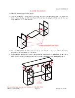
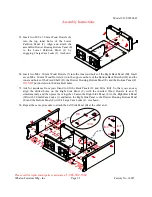
40.


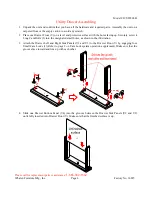
Insert two M8 x 30 mm Wood Dowels (4) into the inner end holes of each Drawer Housing Side Panel 

(R) and the Drawer Slide Supports (QL, QM and QR).  


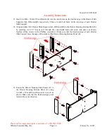
41.


Align the drilled holes underneath Drawer Housing Top Panel (D) with the inserted Wood Dowels (4) 

and press them together. Make sure that the Lid Support Arms (SL and SR) locate between the Drawer 
Housing Side Panels (S) and Drawer Slide Supports (QL and QR) respectively. Fasten the Drawer 
Housing Top Panel (D) to the Drawer Slide Supports (QL, QM and QR) by engaging 6 Cam Locks (2). 
As shown. 


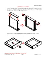
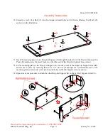
42.


Align the Large Magnetic Catch (13) to the pilot holes under the Drawer Housing Bottom Panel (E) 

with the magnetic plate facing the front of the unit. And then attach the Magnetic Catch (12) in place 
using two #6 x 5/8” Screws (13). 


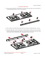
43.


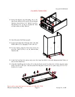
Securely screw two Long Cam Bolts (3) into the designate small holes on the Drawer Housing Bottom 

Panel (E), as shown. 


Summary of Contents for JCS20501-B

Page 1: ...have any questions regarding assembly or if parts are missing DO NOT return this item to the store where it was purchased Please call our toll free customer service number and have your instructions...

Page 2: ...th a rubber mallet IF NECESSARY CAM LOCK SYSTEM OPERATION HOW THE KNOCK DOWN KD ASSEMBLY SYSTEM WORKS 1 Screw the Cam Bolt into the pre drilled small holes on the panel Connect both panels together ma...

Page 3: ...nel 1 BP Left Side Post 1 C Right Side Panel 1 CP Right Side Post 1 D Drawer Housing Top Panel 1 E Drawer Housing Bottom Panel 1 F Bottom Panel 1 G Bottom Front Stretcher 1 H Bottom Back Stretcher 1 I...

Page 4: ...1 SR Right Lid Support Arm 1 T Slide Shelf Support 1 U Pigeon Cube Top Panel 1 U1 Pigeon Cube Outer Panel 2 U2 Pigeon Cube Inner Panel 2 U3 Pigeon Cube Bottom Panel 2 U4 Pigeon Cube Small Shelf 2 Wit...

Page 5: ...extra 9 6 x 1 2 Screw 38 1 extra 10 6 5 x 1 2 Screw 16 1 extra 11 8 x 1 1 4 Screw 8 1 extra 12 8 x 1 1 2 Screw 11 1 extra 13 6 x 5 8 Screw 14 3 4 Ring Shank Nail 15 Small Magnetic Catch 16 Large Magne...

Page 6: ...protective surface with the holes facing up Securely screw 4 Long Cam Bolts 3 into the designated small holes as shown in the illustration 3 Attach the Drawer Left and Right Side Panels V2 and V3 to...

Page 7: ...nel V1 to the Drawer Side Panels V2 and V3 using four 1 1 4 Screws 11 Make sure that the Drawer Bottom Panel V4 fits securely into the groove of the Drawer Back Panel V1 Tighten all the screws with a...

Page 8: ...ge 8 Factory No 16015 Assembly Instructions 8 Place the Pigeon Cube Top Panel U the Pigeon Cube Outer Panels U1 and the Pigeon Cube Inner Panels U2 on a level and protective surface with the holes fac...

Page 9: ...e that the Cam Locks 1 face the bottom of the unit 11 Attach one Pigeon Cube Small Shelf U4 to the Pigeon Cube Outer Panel U1 with two M6 x 30 mm Wood Dowels 5 Make sure that the raw edges on the Pige...

Page 10: ...M6 x 55 mm Wood Dowels 6 on the Pigeon Cube Inner Panels U2 and press them together Make sure that the raw edges point towards the same direction 16 Insert one M6 x 30 mm Wood Dowel 5 into the top inn...

Page 11: ...the unit square 19 Turn over the last assembly on its front edges Unfold the Pigeon Cube Back Panel U6 and lay it to the back edges of the assembled unit Make sure that the overlaps on the panels are...

Page 12: ...plastic release lever of the ball bearing slides up and pull the Slide Runner complete out 22 Using the pilot holes as a guide attach the separated Slide Runners WL and WR to the Sliding Shelf K resp...

Page 13: ...and then press them together Make sure that the outer surfaces are flush with each other Fasten the Left Side Post BP to the Left Side Panel B by engaging four Large Cam Locks 2 26 Repeat the same pr...

Page 14: ...ort T and attach it to the Left Side Panel B using three 1 1 2 Screws 12 Tighten the screw with a Phillips screwdriver Make sure that the front pilot hole is closed to the Left Side Post BP 30 Attach...

Page 15: ...Using the pilot holes as a guide install 2 Door Hinges 20 to the Left and Right Side Posts BP and CP respectively with the flap with cutout to the outside using two 6 5 x 1 2 Screws 10 per hinge flap...

Page 16: ...ttach the Drawer Slide Supports QL QM and QR to the Drawer Housing Bottom Panel E by inserting six 1 1 2 Screws 12 through the countersunk holes and screw into place as shown Tighten all the screws wi...

Page 17: ...gh the right slot of the Drawer Housing Top Panel D making sure the metal bracket on the other end of the Drop Lid Support faces inward 38 Fit the mounting plate of the Drop Lid Support X into the cut...

Page 18: ...together Make sure that the Lid Support Arms SL and SR locate between the Drawer Housing Side Panels S and Drawer Slide Supports QL and QR respectively Fasten the Drawer Housing Top Panel D to the Dra...

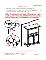
Page 19: ...ts 3 into the designated small holes as shown in the illustration 45 Insert two M8 x 30 mm Wood Dowels 4 into the inner end holes of the Bottom Panel G As shown 46 Align the drilled holes on the Front...

Page 20: ...structions 47 Align and attach the Bottom Back Stretcher H to the Bottom Panel F by using two M8 x 30 mm Wood Dowels 4 and three Large Cam Locks 2 As shown below Make sure that the Cam Locks face outw...

Page 21: ...ls line up 51 Align and attach the Back Panels IL and IR to the Bottom Panel F using four M6 x 30 mm Wood Dowels 5 and four Small Cam Locks 1 As shown Make sure that the Cam Locks face inward 52 Inser...

Page 22: ...he Bottom Back Stretcher H and the inner end holes of the Fixed Shelf D the Drawer Housing Bottom Panel E and the Bottom Panel F DO NOT put dowels into the Cam Bolt holes 55 Ask for assistance from yo...

Page 23: ...bled frame upright 59 Secure the Bottom Back Stretcher H to the Side Panels B and C by engaging 2 Cam Locks 2 60 For nice looking plug five Cam Lock Covers 17 onto the Cams Locks 2 on the Bottom Back...

Page 24: ...and 5 Attach the Top Panel A to the Back Panels IL and IR with 4 Small Cam Locks 1 Fasten the Top Panel A to the Side Panels B and C by engaging four Large Cam Locks 2 65 Attach the Knob 21 to the out...

Page 25: ...th the Slide Tracks and push the drawer carefully inside until it stops NOTE If the drawer does not go in smoothly please take it out and repeat the step If you need to remove the drawer please pull t...

Page 26: ...s are flush with the inner surface of the Drop Lid M 71 Attach the Knob 21 to the outside of the Drop Lid M using the provided Knob Bolt 22 As shown 72 Align and attach the other leaf of Drop down Hin...

Page 27: ...inst the Back Panels IL and IR Make sure you will not scratch the top surface of the Drawer Housing Top Panel D 75 Insert four Shelf Pins 25 into the desired holes in the sides of right bottom compart...

Page 28: ...and the wall As shown in the illustration NOTE Young children can be seriously injured by tipping furniture You must install the Tipping Restraint Hardware with the unit to prevent the unit from tippi...

Page 29: ...ssary Further advice about wood furniture care It is best to keep your furniture in a climate controlled environment Extreme temperature and humidity changes can cause fading warping shrinking and spl...

Page 30: ...20501 B 36 DLS Drop Lid Support JCS20501 B 61 SMC Small Magnetic Catch JCS20501 B 12 RBP Right Back Panel JCS20501 B 37 UDSS Utility Drawer Slides with Screws JCS20501 B 62 LMC Large Magnetic Catch JC...

Reviews: