background image

Model # SPUS-LDHL-LF 

Please call for replacement parts or assistance: 

1-866-942-5362


Whalen Furniture Mfg., Inc.   


     Page 10 


     Factory No. 15548 

Assembly Instructions 


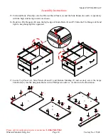
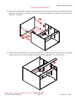
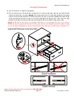
15.


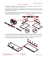
Fit Guide Rails (P and Q) onto the Drawer Back Panels (J) and the Side Panels (K and L) respectively 
with the high side facing inward. As shown. 


16.


Hook two File Hangers (R) onto the high edge of Guide Rails (O and P). Slide the File Hangers left and 
right to keep hanging files organized. 


17.


Locate Top Panel (A), Side Panels (B and C) and Bottom Molding (F) and securely screw the Large 
Cam Bolts (4) into the designated holes with a Phillips screwdriver. As shown in the illustration. 


P

R

K

L

I

R

Q

Q

Q

P

R

K/L

J

J

P

R

K

L

I

R

Q

Q

J

B

4

4

4

4

4

4

4

4

4

4

4

4

4

A

C

F

Summary of Contents for Leadenhall Lateral File

Page 1: ...ts are missing DO NOT return this item to the store where it was purchased Please call our toll free customer service number and have your instructions and parts list ready to provide the model name p...

Page 2: ...material before discarding carton Remove any remaining staples from the carton before discarding Remove all parts from carton and separate into groups as indicated on part list Please ensure all parts...

Page 3: ...g lightly with a rubber mallet IF NECESSARY CAM LOCK SYSTEM OPERATION HOW THE KNOCK DOWN KD ASSEMBLY SYSTEM WORKS 1 Screw the Cam Bolt into the threaded inserts on the panel Connect both panels togeth...

Page 4: ...hardware are present before beginning assembly A Top Panel 1 B Left Side Panel 1 C Right Side Panel 1 D Upper Back Panel 1 E Lower Back Panel 1 F Bottom Molding 1 G Bottom Stretcher 1 H Middle Crossba...

Page 5: ...Cam Lock 2 Large Cam Lock 3 Small Cam Bolt 4 Large Cam Bolt 12 1 extra 22 1 extra 12 1 extra 22 1 extra 5 M8 x 30 mm Wood Dowel 6 6 x 1 2 Screw 7 8 x 5 8 Screw 8 10 x 1 1 4 Wood Screw 19 1 extra 42 2...

Page 6: ...slides up and pull the Slide Runner complete out 3 Attach the separated Slide Runners S to the Drawer Side Panels K and L respectively with three 1 2 Screws 6 per slide runner Make sure that the slid...

Page 7: ...Right Side Panels K and L to the Drawer Front I by engaging four Small Cam Locks 1 Refer to page 3 on Cam Lock system operation supplement As shown Make sure that the grooves line up with each other...

Page 8: ...r Side Panels K and L until fully inserted into the Drawer Front I Make sure the finished surface will face up As shown 9 Fasten one Drawer Back Panel J to the Drawer Side Panels K and L and Drawer Bo...

Page 9: ...Handle Bolts 12 12 Repeat the same procedure to assemble the other drawer 13 Using the pilot holes as a guide attach one Lock Holder 14 to one Drawer Left Side Panel K with two 1 2 Screws 6 Make sure...

Page 10: ...with the high side facing inward As shown 16 Hook two File Hangers R onto the high edge of Guide Rails O and P Slide the File Hangers left and right to keep hanging files organized 17 Locate Top Pane...

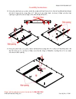
Page 11: ...e Left and Right Side Panels B and C respectively using three 1 2 Screws 6 per slide track As shown Make sure the slide opening is against the closest edge of the Side Panels B and C 19 Using the pilo...

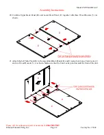
Page 12: ...embly Instructions 20 Combine Upper Back Panel D and Lower Back Panel E together with three Wood Dowels 5 As shown 21 Attach the Left Side Panel B to the assembled Back Panels D and E using four Large...

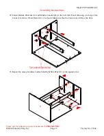
Page 13: ...o 15548 Assembly Instructions 22 Fasten Bottom Stretcher G and Middle Crossbar H to the Left Side Panel B using two Large Cam Locks 2 and two Wood Dowels 5 As shown Make sure that the Cam Locks will f...

Page 14: ...the top inner holes of the Side Panels B and C and the Upper Back Panel D Position the Top Panel A onto the inserted Wood Dowels 5 and lock with seven Cam Locks 2 As shown 25 Fasten the Bottom Molding...

Page 15: ...ttom Molding F to both Side Panels B and C by attaching two Corner Connectors 9 at the joints using two 1 2 Screws 6 per connector As shown 27 Gently tap two Floor Protectors 10 to the bottom of each...

Page 16: ...the Left Side Panel K To insert the drawer into place extend the Ball Bearing Slide Tracks on the Side Panels B and C all the way forward including ball bearing cart Then align the Slide Runners on t...

Page 17: ...g Restraint Hardware to attach the tip over restraint to the unit and the wall NOTE Young children can be seriously injured by tipping furniture You must install the Tipping Restraint Hardware with th...

Page 18: ...ther advice about wood furniture care It is best to keep your furniture in a climate controlled environment Extreme temperature and humidity changes can cause fading warping shrinking and splitting of...

Page 19: ...sbar SPUS LDHL LF 27 1 1 4WS 10 x 1 1 4 Wood Screw SPUS LDHL LF 9 DF Drawer Front SPUS LDHL LF 28 CC Corner Connector SPUS LDHL LF 10 DBP Drawer Back Panel SPUS LDHL LF 29 FP Floor Protector SPUS LDHL...

Reviews: