background image


Assembly Instructions 


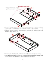
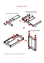
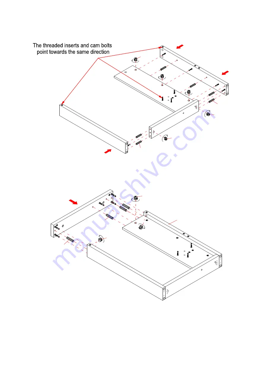
4.


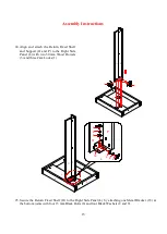
Glue four 30 mm Wood Dowels (3) to the Left Back Panel (F) and attach it to the previous assembly by 
engaging four Cam Locks (1) (Refer to page 3 on Cam Lock system operation supplement). 

5.


Fasten  the  Left  Front  Panel  (E)  to  the  front  end  of  Left  Bottom  Panel  (D)  using  two  30  mm  Wood 
Dowels (3) and one Cam Lock (1). 


6.


Glue four 30 mm Wood Dowels (3) into the drilled holes on the top edge of the previous assembly.  

7.


Align the drilled holes on the Left Top Panel (C) with the inserted Wood Dowels (3) and press them 
together. Fasten the Left Top Panel (C) in place by engaging four Cam Locks (1).  

1

G

D

F

E

1

3

3

1

3

1

1

3

C

G

D

F

E

Summary of Contents for ODUS-JLDHCV

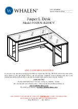
Page 1: ...DO NOT return this item to the store where it was purchased Please call our toll free customer service number and have your instructions and parts list ready to provide the model name part name or factory number 1 866 942 5362 Pacific Standard Time 8 30 a m 4 30 p m Monday Friday Or visit our web site 24 hours a day 7 days a week for product assistance at www whalenfurniture com Or e mail your req...

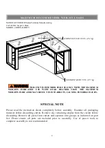
Page 2: ...iscarding Remove all parts from carton and separate into groups as indicated on part list Please ensure all parts are included prior to assembly Use of power tools to complete assembly is not recommended MAXIMUM LOAD 100 lb 45 4 kg MAXIMUM RECOMME NDE D WE IGHT LOADS THIS UNIT IS INTENDED FOR USE ONLY WITH THE MAXIMUM WEIGHTS INDICATED USE WITH LOAD HEAVIER THAN THE MAXIMUM WEIGHTS INDICATED MAY R...

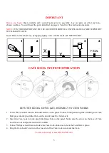
Page 3: ...ERATION HOW THE KNOCK DOWN KD ASSEMBLY SYSTEM WORKS 1 Screw the Cam Bolt into the threaded inserts on the panel Connect both panels together making sure Cam Bolt goes into the pre drilled hole on the end of panel for Cam Lock 2 Insert the Cam Lock into the pre drilled large hole on the panel Make sure the arrow on the face of Cam Lock faces out and points towards Cam Bolt 3 Take a Phillips screwdr...

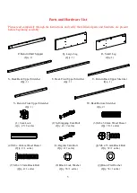
Page 4: ...lass Top B Return Glass Top C Left Top Panel Qty 1 Qty 1 Qty 1 D Left Bottom Panel E Left Front Panel F Left Back Panel Qty 1 Qty 1 Qty 1 G Left Side Panel H Right Top Panel I Right Bottom Panel Qty 1 Qty 1 Qty 1 J Right Front Panel K Right Back Panel L Right Side Panel Qty 1 Qty 1 Qty 1 M Desk Fixed Shelf N Desk Shelf Support O Return Fixed Shelf Qty 1 Qty 1 Qty 1 ...

Page 5: ... Front Upper Stretcher U Return Back Upper Stretcher Qty 1 Qty 1 Qty 1 V Return Front Upper Stretcher W Back Bottom Stretcher Qty 1 Qty 2 1 Cam Lock 2 Self tapping Cam Bolt 3 M8 x 30 mm Wood Dowel Qty 45 2 extra Qty 41 2 extra Qty 36 1 extra 4 M8 x 40 mm Wood Dowel 5 Regular Cam Bolt 6 M6 x 15 mm Black Bolt Qty 2 1 extra Qty 4 1 extra Qty 32 1 extra 7 M6 x 32 mm Black Bolt 8 Black Lock Washer 9 Bl...

Page 6: ...xtra 13 Zinc Flat Washer 14 M4 x 20 mm Screw 15 M5 x 50 mm Screw Qty 17 1 extra Qty 16 1 extra Qty 4 1 extra 16 M5 x 12 mm Screw 17 Square Metal Bracket 18 L shaped Metal Bracket Qty 8 1 extra Qty 4 Qty 2 19 Straight Metal Bracket 20 Left Metal Bracket 21 Right Metal Bracket Qty 2 Qty 2 Qty 2 22 Cam Lock Cover 23 Cam Lock Cap Flat Tip Hex Wrench Qty 8 1 extra Qty 15 1 extra Qty 1 Glue Qty 2 Tools ...

Page 7: ...r the empty carton to avoid any scratch 2 Lay out the Left Side Frame components C E F and G with the holes facing up Securely screw the Self tapping Cam Bolts 2 into the designated small holes as shown in the illustration 3 Glue one 30 mm Wood Dowel 3 into the bottom middle hole of the Left Side Panel G and attach it to the Left Bottom Panel D with two 50 mm Screws 15 Tighten the screws with a Ph...

Page 8: ...the Left Front Panel E to the front end of Left Bottom Panel D using two 30 mm Wood Dowels 3 and one Cam Lock 1 6 Glue four 30 mm Wood Dowels 3 into the drilled holes on the top edge of the previous assembly 7 Align the drilled holes on the Left Top Panel C with the inserted Wood Dowels 3 and press them together Fasten the Left Top Panel C in place by engaging four Cam Locks 1 1 G D F E 1 3 3 1 3 ...

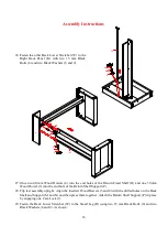
Page 9: ...oints of Left Bottom Panel D by using four 20 mm Screws 14 per bracket 10 Secure the Left Top Panel C to the Left Back Panel F by engaging one Cam Lock 1 11 Securely screw the Self tapping Cam Bolts 2 into the designated small holes on the Right Side Frame components H J K and L as shown in the illustration 2 H L K J 1 C F E D 17 14 G 17 14 ...

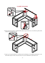
Page 10: ...10 Assembly Instructions 12 Repeat the same procedure to form the Right Side Frame L I K J H 3 1 1 3 1 L I K J 1 3 3 1 L I 15 3 1 17 14 K J I H L 17 14 ...

Page 11: ...O Legs Q and R and Desk Shelf Support N as shown 14 Glue two 30 mm Wood Dowels 3 into the inner holes of the Return Shelf Support P and attach it to the Return Fixed Shelf O by engaging three Cam Locks 1 15 Repeat the same procedure to attach the Desk Shelf Support N to the Desk Fixed Shelf M M N 1 1 1 3 3 1 3 O P 3 1 1 2 O M N Q R ...

Page 12: ...oles as a guide attach two Straight Metal Brackets 19 to the Desk Fixed Shelf M with four 12 mm Screws 16 17 Align and attach the previous assembly to the Small Leg R with two 30 mm Wood Dowels 3 and three Cam Locks 1 as shown M N 19 16 3 1 M N R ...

Page 13: ...Large Leg Q to the Small Leg R and Desk Fixed Shelf M with three 30 mm Wood Dowels 3 and five Cam Locks 1 19 Fasten one Back Lower Stretcher W to the Large Leg Q using two 15 mm Black Bolts 6 and two Black Washers 8 and 9 1 1 3 3 R M N Q 6 8 9 W Q R M ...

Page 14: ...wels 3 and three Cam Locks 1 22 Fasten the Back Lower Stretcher W to the Left Back Panel F using two 15 mm Black Bolts 6 and two Black Washers 8 and 9 23 Secure the Desk Fixed Shelf M to the Left Side Panel G by attaching one L shape Metal Bracket 18 at the bottom joints with four 15 mm Black Bolts 6 and four Black Washers 8 and 9 6 8 9 1 3 M N W G D E F 6 8 9 6 8 9 M 18 G N M N G D F ...

Page 15: ...Right Side Panel L with two 30 mm Wood Dowels 3 and three Cam Locks 1 25 Secure the Return Fixed Shelf O to the Right Side Panel L by attaching one Metal Bracket 18 at the bottom joints with four 15 mm Black Bolts 6 and four Black Washers 8 and 9 3 1 1 L I K J O P 6 8 9 6 8 9 L 18 O P L I K J O P ...

Page 16: ... Dowel 3 into the end hole of the Return Shelf Support P 28 Flip last assembly upright Align the inserted Wood Dowels 3 and 4 with the drilled holes on the Desk Shelf and Support M and N and then press them together Attach the Return Shelf Support P in place by engaging one Cam Lock 1 29 Fasten the Back Lower Stretcher W to the Small Leg R using two 15 mm Black Bolts 6 and two Black Washers 8 and ...

Page 17: ...m Screws 16 31 Ask for assistance to flip around the assembled unit upright 32 Fasten the Left and Right Metal Brackets 20 and 21 to the upper corners of assembled side frames by using two 15 mm Black Bolts 6 and two Black Washers 8 and 9 per bracket K J H C E F 21 20 20 21 20 21 6 8 9 6 8 9 C H 19 16 O P M N ...

Page 18: ...lign and attach the Desk Back Upper Stretcher S to the Large Leg Q by using two Cam Locks 1 You may need to adjust the height of Regular Cam Bolts 5 when assembling 35 Fasten the Desk Back Upper Stretcher S to the installed Right Metal Bracket 21 with two 15 mm Black Bolts 6 and two Black Washers 8 and 9 5 S U S Q R C E F S 1 Q S 6 8 9 21 ...

Page 19: ...her U to the Small Leg R and the installed Left Metal Bracket 20 37 Insert two 50 mm Zinc Bolts 11 with the Zinc Flat Washers 13 through the drilled holes on the Return Back Upper Stretcher U and securely screw into the Desk Back Upper Stretcher S Q R U K J H 1 U R U 6 8 9 20 Q R U S U S 11 13 ...

Page 20: ...t Washers 13 39 Fasten the Desk Front Upper Stretcher T to the installed Left Metal Bracket 20 with two 15 mm Black Bolts 6 and two Black Washers 8 and 9 40 Repeat the same procedure to attach the Return Front Upper Stretcher V to the Desk Front Upper Stretcher T and the installed Right Metal Bracket 21 U T C E F T 6 8 9 20 U T 11 13 K J H T V V 6 8 9 21 11 13 V T ...

Page 21: ...r 32 mm Bolts 7 with the Black Washers 8 and 9 through the drilled holes on both Top Panels C and H and insert eleven 35 mm Zinc Bolts 10 with the Zinc Washers 12 and 13 through the Upper Stretchers S T U and V and securely screw into place 42 Plug Cam Lock Covers 22 and Cam Lock Caps 23 onto the visible Cams Locks to conceal the Cams 7 8 9 C H A B S T U V 10 12 13 V C H T U S B A A B 23 22 ...

Page 22: ...limate controlled environment Extreme temperature and humidity changes can cause fading warping shrinking and splitting of wood It is advised to keep furniture away from direct sunlight as sun may damage the finish Proper care and cleaning at home will extend the life of your purchase Following these important and helpful tips will enhance your furniture as it ages We hope you enjoy your purchase ...

Reviews: