background image

11 

F

E

L

1

1

Assembly Instructions 


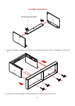
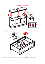
13.


Attach the Middle Crossbar (L) between the Lower Partition Panels (E and F) by engaging two Cam Locks 
(1). 


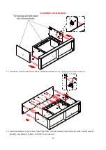
14.


Attach the previous assembly to the Bottom Panel (C) with four 50 mm Screws (6). 
  

E

F

C

6

6

6

6

Summary of Contents for Sedona MNFP54BF23-5

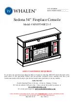
Page 1: ...issing DO NOT return this item to the store where it was purchased Please call our toll free customer service number and have your instructions and parts list ready to provide the model name part name...

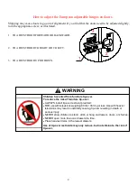
Page 2: ...ied from furniture tip over To reduce the risk of furniture tip over ALWAYS install tip over restraint provided FOR use with televisions weighing 80 lbs 36 3 kg or less Use with heavier televisions ma...

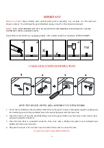
Page 3: ...KNOCK DOWN KD ASSEMBLY SYSTEM WORKS 1 Screw the Cam Bolt into the pre drilled small holes on the panel Connect both panels together making sure the Cam Bolt goes into the pre drilled hole at the end o...

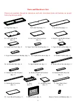
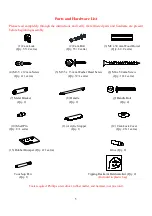
Page 4: ...Panel Qty 2 H Upper Side Panel Molding Qty 2 I Upper Partition Panel Qty 1 J Upper Partition Panel Molding Qty 1 K Top Reinforcement Qty 1 L Middle Crossbar Qty 1 M Left Middle Stile Qty 1 N Right Mi...

Page 5: ...3 5 x 12 mm Screw 5 M3 5 x 15 mm Washer Head Screw 6 M4 x 50 mm Screw Qty 4 1 extra Qty 32 1 extra Qty 10 1 extra 7 Metal Bracket 8 Handle 9 Handle Bolt Qty 2 Qty 2 Qty 4 10 Shelf Pin 11 Acrylic Stopp...

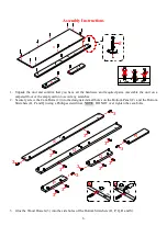
Page 6: ...y carton to avoid any scratches 2 Securely screw the Cam Bolts 2 into the designated small holes on the Bottom Panel C and the Bottom Stretchers O P and Q using a Phillips screwdriver NOTE DO NOT over...

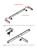
Page 7: ...tions 4 Attach the Bottom Back Stretcher S between the Bottom Side Stretchers P and Q by engaging two Cam Locks 1 5 Align and attach the Bottom Middle Stretcher R to the Bottom Front Stretcher O by en...

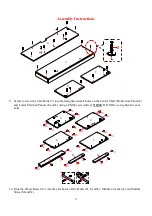
Page 8: ...ttom Side Stretchers P and Q by engaging two Cam Locks 1 7 Fasten the Bottom Back Stretcher S to the Bottom Middle Stretcher R with two 50 mm Wood Screws 6 8 Attach the assembled base to the bottom pa...

Page 9: ...B Bottom Panel C and Lower Partition Panels E and F using a Phillips screwdriver NOTE DO NOT over tighten the cam bolts 10 Glue the Wood Dowels 3 into the side holes of the Panels D E and F Middle Cro...

Page 10: ...Assembly Instructions 11 Attach the Left Middle Stile M to the Left Lower Partition Panel E by engaging two Cam Locks 1 12 Attach the Right Middle Stile N to the Right Lower Partition Panel F by engag...

Page 11: ...sembly Instructions 13 Attach the Middle Crossbar L between the Lower Partition Panels E and F by engaging two Cam Locks 1 14 Attach the previous assembly to the Bottom Panel C with four 50 mm Screws...

Page 12: ...ch the Lower Side Panels D to the Bottom Panel C by engaging the Cam Locks 1 16 Ask for assistance to place the Center Shelf B onto the inserted wood dowels on the vertical panels properly and fasten...

Page 13: ...d small holes on the Center Shelf B and Moldings H and J using a Phillips screwdriver NOTE DO NOT over tighten the cam bolts 19 Glue the Wood Dowels 3 into the side holes of the Panels G and I Top Rei...

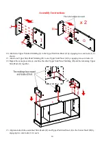
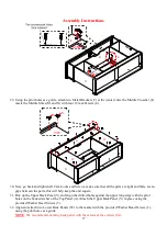
Page 14: ...ne Upper Side Panel Molding H to one Upper Side Panel G by engaging two cam locks 1 22 Repeat the same procedure to combine the other Upper Side Panel Molding H and the remaining Upper Side Panel G to...

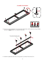
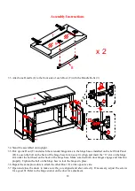
Page 15: ...screw the Cam Bolts 2 into the designated small holes on the Top Panel A using a Phillips screwdriver NOTE DO NOT over tighten the cam bolts 25 Attach the Top Reinforcement K to the Top Panel A with...

Page 16: ...he inserted Wood Dowels 3 and fasten it in place by engaging six Cam Locks 1 27 Ask for assistance to lay down the assembled unit at its front edges 28 Fasten the Middle Crossbar L to the Center Shelf...

Page 17: ...rts this will help keep the unit square 31 Pick up the Upper Back Panel V and align the drilled holes against the upper long edge with the pilot holes on the back stretcher of the Top Panel A Attach t...

Page 18: ...asy fit Align and insert the U slot on the hinge arm under the bolt head on the back of the hinge base Make sure that both door hinges engage and function properly Tighten the bolt on the hinge base t...

Page 19: ...lf Pins 10 at the same level so the shelf is not tilted Tilt and rest the Adjustable Shelves U onto the Shelf Pins 10 39 Stick the Rubber Bumpers 13 at the outer corners of both Doors T where they mee...

Page 20: ...fireplace insert to the mantel with six insert screws as shown NOTE To prevent your TV from tipping you must follow these instructions if you place a TV on top of your console Otherwise skip to Step...

Page 21: ...to a wall stud Depending upon your wall construction different anchor hardware maybe required Please contact your local hardware store for assistance Young children can be seriously injured by tipping...

Page 22: ...result in death or serious injury due to furniture collapse or over turning onto a child NEVER place a TV on furniture that is not intended to support a TV NEVER exceed the maximum size and weight of...

Page 23: ...day www whalenfurniture com MAXIMUM RECO MMENDED WEIGHT LOADS THIS UNIT IS NOT INTENDED FOR USE WITH CRT TVS USE ONLY WITH FLAT PANEL TVS AND AUDIO VIDEO EQUIPMENT MEETING RECOMMENDED SIZE AND WEIGHT...

Page 24: ...screws periodically and tighten them if necessary Further Advice about Wood Furniture Care It is best to keep your furniture in a climate controlled environment Extreme temperature and humidity chang...

Reviews: