background image


22 


Assembly Instructions 


NOTE:

 The adjustable shelf (H) is designed to put into either compartment. 

19.


Depending on your configuration, insert two Shelf Pins (10) into the holes at the desired height on the 
desired Partition Panel (F). 

20.


 Securely screw two Shelf Pins (11) into the holes on the Large Leg (E). Make sure you place the Shelf 
Pins (10 and 11) in the same level, so that they will hold the Adjustable Shelf (H) properly.  

21.


Tilt and rest the Adjustable Shelf (H) onto the Shelf Pins (10 and 11). 


x 2


x 2


H

10

11

H

H

E

F

F

E

Summary of Contents for WHA-10005

Page 1: ...sing DO NOT return this item to the store where it was purchased Please call our customer service number and have your instructions and parts list ready to provide the model name part name or factory...

Page 2: ...re discarding Remove all parts from carton and separate into groups as indicated on part list Please ensure all parts are included prior to assembly Use of power tools to complete assembly is not reco...

Page 3: ...ION HOW THE KNOCK DOWN KD ASSEMBLY SYSTEM WORKS 1 Screw the Cam Bolt into the threaded inserts on the panel Connect both panels together making sure Cam Bolt goes into the pre drilled hole on the end...

Page 4: ...will not be pinched or damaged when the desk is pushed to the wall Make sure cord is not pinched between desk and floor Use the unit for indoor use only Do not use an extension cord to connect this u...

Page 5: ...e or more of the following measures Reorient or relocate the receiving antenna Increase the separation between the equipment and receiver Connect the equipment into an outlet on a circuit different fr...

Page 6: ...ry Hook Qty 1 K Cable Wheel Qty 2 L Power Center Qty 1 1 Cam Lock 2 Cam Bolt 3 M6 x 30 mm Wood Dowel 4 M4 x 32 mm Screw Qty 4 1 extra Qty 4 1 extra Qty 2 1 extra Qty 4 1 extra 5 1 4 x 5 8 Bolt 6 Lock...

Page 7: ...nfirm that you have all the hardware and required parts Assemble the unit on a carpeted floor or the empty carton to avoid any scratch 2 Securely screw the Cam Bolts 2 into the threaded bushing on the...

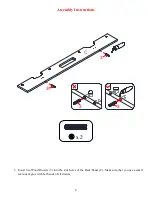
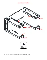
Page 8: ...8 Assembly Instructions 3 Insert two Wood Dowels 3 into the side holes of the Back Panel C Make sure that you use a small amount of glue with both ends of all dowels x 2 3 3 3 3 C...

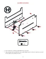
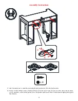
Page 9: ...9 Assembly Instructions 4 Align and attach the Back Panel C to the Desk Top A by engaging four Cam Locks 1 Refer to page 3 on Cam Lock system operation supplement x 4 1 A C C A...

Page 10: ...bly Instructions 5 Feed the wire of Power Center L through the cutout of the Back Panel C and push into the cutout Secure it in place with two 15 mm Screws 9 Make sure the wire is not pinched x 2 L C...

Page 11: ...s 6 Ask for assistance to stand the assembled Desk Top A vertical 7 Align and attach the Fixed Shelf B to the assembled Back Panel C with four 32 mm Screws 4 and securely tighten with a Philips screwd...

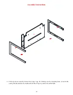
Page 12: ...ssembly Instructions 8 Fit the previous assembly between the Large Legs E Making sure the mounting holes of metal tabs overlap the threaded inserts underneath the Desk Top A and the Fixed Shelf B B A...

Page 13: ...13 Assembly Instructions 9 Fasten the Desk Top A and the Fixed Shelf B into place with eight 5 8 Bolts 5 and eight Washers 6 and 7 B A E E 5 6 7 x 8 x 8 x 8...

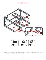
Page 14: ...ssembly Instructions 10 Fit the return of Small Legs D onto U shaped brackets of Large Legs E and fasten them into place with four 5 8 Bolts 5 and four Washers 6 and 7 x 4 x 4 x 4 D D D D E E B E D 5...

Page 15: ...15 Assembly Instructions 11 Fasten the Small Legs D to the Fixed Shelf B with four 5 8 Bolts 5 and four Washers 6 and 7 x 4 x 4 x 4 B D D D D 5 6 7...

Page 16: ...16 Assembly Instructions 12 Align and attach the Bottom Panels G to the Legs D and E with eight 5 8 Bolts 5 and eight Washers 6 and 7 x 8 x 8 x 8 D D E E 5 6 7 G G D D...

Page 17: ...7 Assembly Instructions 13 Insert the Partition Panels F to against the Small Legs D Make sure that the mounting holes on Small Legs D align with the threaded inserts on Partition Panels F properly F...

Page 18: ...18 Assembly Instructions 14 Fasten the Partition Panels F into place with eight 1 1 8 Bolts 8 x 8 8 F F D D D D D F...

Page 19: ...19 Assembly Instructions 15 Align and attach the Cup Holder I and the Accessory Hook J to the Fixed Shelf B with five 5 8 Bolts 5 and five Washers 6 and 7 x 5 x 5 x 5 5 B I J B 6 7...

Page 20: ...20 Assembly Instructions 16 Attach the Floor Levelers 12 to the bottom of the Small Legs D x 4 12 D 12 12 12 D D D...

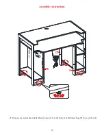
Page 21: ...pright and position it at the desired location 18 Fasten 2 Cable Wheels K to the Back Panel C with four 15 mm Screws 9 The cable wheels allow you to organize route and separate your component cords an...

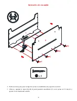
Page 22: ...into the holes at the desired height on the desired Partition Panel F 20 Securely screw two Shelf Pins 11 into the holes on the Large Leg E Make sure you place the Shelf Pins 10 and 11 in the same lev...

Page 23: ...23 Assembly Instructions 22 If necessary adjust the installed floor levelers 12 at the bottom of the Small Legs D to level the unit D D D...

Page 24: ...iture Care It is best to keep your furniture in a climate controlled environment Extreme temperature and humidity changes can cause fading warping shrinking and splitting of wood It is advised to keep...

Page 25: ...o al establecimiento donde lo adquiri Por favor llame a nuestro n mero de servicio al cliente y tienen sus instrucciones y lista de piezas listo para proporcionar el nombre del modelo el nombre o el n...

Page 26: ...ijado al cart n antes de tirarlo Una vez apartadas las piezas sep relas en grupos como se indica en la lista Cerci rese de que tiene todas las piezas antes de comenzar el ensamblaje No se recomienda u...

Page 27: ...MO FUNCIONA LA INSTALACI N DE MONTAJE KD 1 Fijar los tornillos de fijaci n en los orificios peque os Conectar ambos paneles cerciorandose que los tornillos de fijaci n entren bien y que estos queden e...

Page 28: ...do el escritorio se empuja hacia la pared Aseg rese de que el cable no est aplastado entre el escritorio y el piso Utilice la unidad solo para interiores No utilice una para conectar esta unidad a un...

Page 29: ...te una o m s de las siguientes medidas Reorientar o reubicar la antena receptora Aumente la separaci n entre el equipo y el receptor Conecte el equipo a una toma de corriente en un circuito diferente...

Page 30: ...ables Cant 2 L Centro de poder Cant 1 1 Tuerca de fijaci n 2 Perno de fijaci n 3 Clavija de madera de M6 x 30 mm 4 Perno de M4 x 32 mm Cant 4 1 extra Cant 4 1 extra Cant 2 1 extra Cant 4 1 extra 5 Per...

Page 31: ...iene todo el material de ferreter a y partes requeridas Ensamblar la unidad en un piso alfombrado o en el cart n vac o para evitar rasgu os 2 Atornillar los pernos de fijaci n 2 en los espacios roscad...

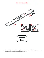
Page 32: ...Instructivo de ensamble 3 Insertar 2 clavijas de madera 3 en los agujeros laterales del panel posterior C Asegurar de usar una cantidad peque a de pegamento en ambos lados de las clavijas x 2 3 3 3 3...

Page 33: ...9 Instructivo de ensamble 4 Alinear y adjuntar el panel posterior C a la tapa del escritorio A empleando 4 tuercas de fijaci n 1 Consulte la p gina 3 del sistema de tuerca de fijaci n x 4 1 A C C A...

Page 34: ...ensamble 5 Meter el cable del centro de poder L a trav s de del recorte del panel posterior C y empujar en el recorte Asegurar en su lugar con 2 pernos de 15 mm 9 Asegurar que el cable no est apretad...

Page 35: ...dir asistencia para poner la tapa del escritorio ensamblada A en posici n vertical 7 Alinear y adjuntar la repisa fija B al panel posterior ensamblado C con 4 pernos de 32 mm 4 y apretar con el desarm...

Page 36: ...mble 8 Meter el ensamble previo entre las patas largas E Asegurar que los agujeros de montaje de las pesta as de metal est n sobre los insertos roscados abajo de la tapa del escritorio A y sujetar la...

Page 37: ...13 Instructivo de ensamble 9 Sujetar la tapa del escritorio A y la repisa fija B en su lugar con 8 pernos de 5 8 5 y 8 arandelas 6 y 7 B A E E 5 6 7 x 8 x 8 x 8...

Page 38: ...ctivo de ensamble 10 Meter la parte inferior de las patas cortas D en los soportes U de las patas largas E y sujetarlos en su lugar con 4 pernos de 5 8 5 y 4 arandelas 6 y 7 x 4 x 4 x 4 D D D D E E B...

Page 39: ...15 Instructivo de ensamble 11 Sujetar las patas cortas D a la repisa fija B con 4 pernos de 5 8 5 y 4 arandelas 6 y 7 x 4 x 4 x 4 B D D D D 5 6 7...

Page 40: ...16 Instructivo de ensamble 12 Alinear y adjuntar los paneles inferiores G a las patas D y E con 8 pernos de 5 8 5 y 8 arandelas 6 y 7 x 8 x 8 x 8 D D E E 5 6 7 G G D D...

Page 41: ...ensamble 13 Insertar los paneles divisores F en contra a las patas cortas D Asegurar que los agujeros de montaje en las patas cortas D se alineen con los insertos roscados en los paneles divisores F a...

Page 42: ...18 Instructivo de ensamble 14 Sujetar los paneles divisores F en su lugar con 8 pernos de 1 1 8 8 x 8 8 F F D D D D D F...

Page 43: ...19 Instructivo de ensamble 15 Alinear y adjuntar el portavasos I y el gancho para accesorios J a la repisa fija B con 5 pernos de 5 8 5 y 5 arandelas 6 y 7 x 5 x 5 x 5 5 B I J B 6 7...

Page 44: ...20 Instructivo de ensamble 16 Adjuntar los niveladores de piso 12 a la parte inferior de las patas cortas D x 4 12 D 12 12 12 D D D...

Page 45: ...sici n vertical y en el lugar deseado 18 Sujetar 2 gu as de cables K al panel posterior C con 4 pernos de 15 mm 9 Las gu as de cables le permiten organizar encaminar y separar sus cables y cordones de...

Page 46: ...10 en los agujeros a la altura deseada en el panel divisor deseado F 20 Atornillar 2 pernos de repisa 11 en los agujeros en las patas largas E Asegurar de poner los pernos de repisa 10 y 11 en el mis...

Page 47: ...23 Instructivo de ensamble 22 Si fuera necesario ajustar los niveladores de piso instalados 12 en la parte inferior de las patas cortas D para nivelar la unidad D D D...

Page 48: ...e humedad pueden causar cambios como partes pandas molduras que se contraigan o que la madera se raje Es recomendable mantener la unidad lejos del sol directo ya que puede da ar el acabado Cuidados ad...

Reviews: