background image


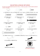
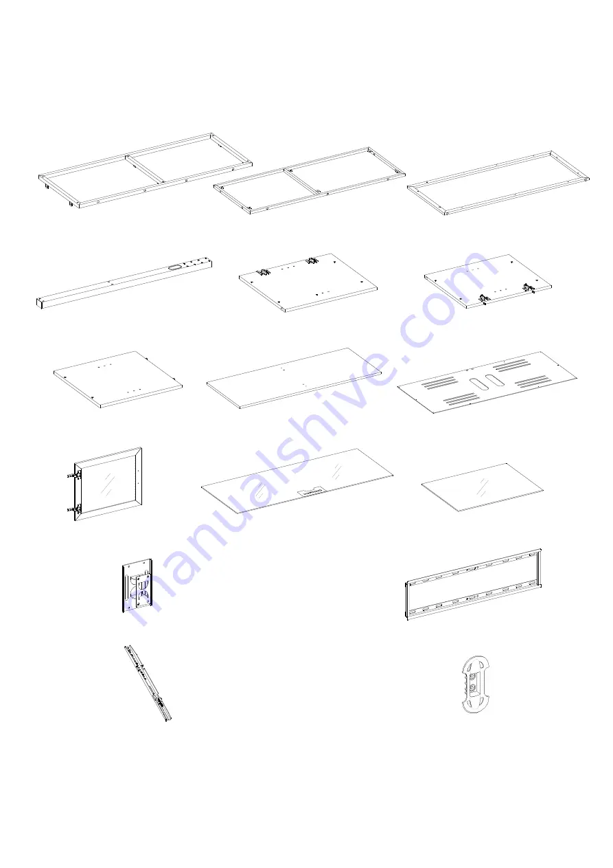
Lista de Partes y Artículos de Ferretería 


Por favor lea completamente las instrucciones y verifique que estén todas las partes antes de 
iniciar el ensamble. 


A- REPISA SUPERIOR


(1)      B- REPISA METÁLICA INFERIOR (1)     C- REPISA FRONTAL (1)  


               D- POSTE (1)                       E- PANEL IZQUIERDO (1)               F- PANEL DERECHO (1) 


G- PANEL DIVISOR (1) 

        H- PANEL INFERIOR (1)                    I- RESPALDO (1) 


       J- PUERTA (2)                         K- VIDRIO SUPERIOR (1)              L- REPISA DE VIDRIO (2) 


M- SOPORTE GIRATORIO (1)                                                  N- MARCO DE MONTAJE (1)   


O- SOPORTE MONITOR (2)                                                      P- Guía Para Cable (2) 

Summary of Contents for XLCD-15

Page 1: ... to use this TV Console in different configurations at a later date if desired ADULT ASSEMBLY REQUIRED If you have any questions regarding assembly or if parts are missing DO NOT return this item to the store where it was purchased Please call our toll free customer service number and have your instructions and parts list ready to provide the model name part name or factory number 866 942 5362 Pac...

Page 2: ...55 FLAT PANEL TVs WITHOUT SWIVELING BRACKET MAXIMUM LOAD 135 lb 61 2 kg MAXIMUM LOAD 50 lb 22 6 kg PLACE TV BEHIND THE STOPPER THIS UNIT IS NOT INTENDED FOR USE WITH CRT TVS USE ONLY WITH FLAT PANEL TVS AND AUDIO VIDEO EQUIPMENT MEETING RECOMMENDED SIZE AND WEIGHT LIMITS NEVER USE WITH LARGER HEAVIER THAN RECOMMENDED FLAT PANEL TVS OR EQUIPMENT TO AVOID INSTABILITY PLACE FLAT PANEL TV IN THE CENTR...

Page 3: ... before beginning assembly A TOP SHELF FRAME 1 B BOTTOM METAL FRAME 1 C FRONT FRAME 1 D SPINE 1 E LEFT SIDE PANEL 1 F RIGHT SIDE PANEL 1 G DIVIDER PANEL 1 H BOTTOM PANEL 1 I BACK PANEL 1 J DOOR PANEL 2 K TOP GLASS 1 L ADJUSTABLE GLASS SHELF 2 M SWIVELING BRACKET 1 N MOUNTING FRAME 1 O MONITOR BRACKET 2 P CABLE WHEEL 2 ...

Page 4: ...OLT 14 1 extra 4 1 BOLT 7 1 extra 5 1 1 4 BOLT 4 1 extra 6 2 1 4 BOLT 4 1 extra 7 LOCK WASHER 8 FLAT WASHER 9 2 SCREW 22 1 extra 22 1 extra 2 1 extra 10 1 2 SCREW 11 SHELF SUPPORT 12 CONCRETE ANCHOR 16 1 extra 8 1 extra 4 13 2 1 2 LAG BOLT 4 14 LARGE FLAT WASHER 4 1 extra 15 ACRYLIC STOPPER 1 16 HANDLE w BOLTS 2 4 mm HEX WRENCH 2 TOUCH UP PEN 1 TIPPING RESTRAINT HARDWARE KIT 1 Inside Plastic Bag ...

Page 5: ...LT 4 M6 x 12 BOLT 4 M6 x 35 BOLT 4 M8 x 16 BOLT 4 M8 x 40 BOLT 4 M4 LOCK WASHER 4 M5 LOCK WASHER 4 M6 LOCK WASHER 4 M8 LOCK WASHER 4 LARGE SPACER 4 SMALL SPACER 4 M4 M5 FLAT WASHER 8 M6 M8 FLAT WASHER 4 Tools required Hex wrench provided and Phillips screwdriver not provided ...

Page 6: ...n the TOP SHELF FRAME A to the FRONT FRAME C using four 1 1 4 BOLTS 5 with LOCK WASHERS 7 and FLAT WASHERS 8 Make sure that the metal brackets on the TOP SHELF FRAME A and the Floor Levelers on the FRONT FRAME C point towards the same direction 3 Fasten the BOTTOM METAL FRAME B to the FRONT FRAME C with the metal tabs up Use three 1 BOLTS 4 and tighten with the provided HEX WRENCH A B C C UP LOCK ...

Page 7: ... on the TOP SHELF FRAME A and then into the threaded inserts on the LEFT SIDE PANEL E 5 Secure the LEFT SIDE PANEL E to the BOTTOM METAL FRAME B with two 1 BOLTS 4 Tighten all the bolts with the HEX WRENCH provided making sure there are no gaps between the Left Side Panel E and Front Frame C 6 Repeat the same procedure to attach the RIGHT SIDE PANEL F on the other side FLAT WASHER 4 used in this s...

Page 8: ...ly Instructions 7 Using the end dowels as a guide align and attach the DIVIDER PANEL G to the BOTTOM PANEL H using two 2 SCREWS 9 Tighten the screws with a Phillips screwdriver 9 H G 2 SCREW 2 used in this step ...

Page 9: ...nd 8 through the metal brackets on the middle rail of the TOP SHELF FRAME A into the DIVIDER PANEL G 9 Fasten the BOTTOM PANEL H to the BOTTOM METAL FRAME B using six 1 2 SCREWS 10 through the metal tabs FLAT WASHER 2 used in this step LOCK WASHER 2 used in this step 1 2 SCREW 6 used in this step 5 8 BOLT 2 used in this step H G H G ...

Page 10: ... square 11 Position the BACK PANEL I to the back edges of the assembled frame so that the pre drilled holes for the SPINE D overlap the threaded sockets on the TOP SHELF FRAME A Using the pre drill holes on the BACK PANEL I as a guide when attaching with the 1 2 SCREWS 10 NOTE We recommend attaching the back panel with the 1 2 SCREWS at the corners first 1 2 SCREW 10 used in this step ...

Page 11: ...L E 15 Close the doors to double check the alignment If you find that the doors need to be adjusted slightly please refer to the supplement on page 2 and turn the appropriate screws for a perfectly aligned door Once adjusted lock the hinges in place by tighten the bolt on Hinge Base 16 Remove the bolts in the HANDLES 16 and then use the bolts to attach the HANDLES to the outside of the DOOR PANELS...

Page 12: ...the SUCTION CUPS 1 Make sure the top glass is properly centered NOTE If the top glass is scratched you can minimize the damage by using a BLACK marker and filling in the scratched area from underneath 19 Insert the SHELF SUPPORTS 11 into the desired holes on the SIDE PANELS E and F and DIVIDER PANEL G Make sure you place the four SHELF SUPPORTS at the same level so the shelf is not tilted Tilt and...

Page 13: ...onsole 20 If necessary adjust the pre attached FLOOR LEVELERS at the bottom of FRONT FRAME C to level the unit 21 Remove the tape of the ACRYLIC STOPPER 15 and place it in the cut out of the ACRYLIC STOPPER TEMPLATE on the front of the TOP GLASS K Make sure it is properly aligned before applying pressure 22 Remove the ACRYLIC STOPPER template carefully ACRYLIC STOPPER 1 used in this step ...

Page 14: ...d on the plastic bag containing the TIPPING RESTRAINT HARDWARE to mount the tipping restraint to the back rail and the wall NOTE YOU MUST USE THIS TIPPING RESTRAINT TO ATTACH THIS UNIT TO THE WALL TO PREVENT TIPPING CAUSING ACCIDENTS AND OR INJURIES 24 The console is now ready for use Be sure to position your Flat Panel TV in the center of the console behind the ACRYLIC STOPPER NOTE If you choose ...

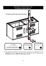
Page 15: ... 6 and four WASHERS 7 and 8 Tighten the bolts with the enclosed hex wrench Make sure the threaded sockets for the CABLE WHEELS P face backward Assembly Instructions for Floating Swivel Mount LOCK WASHER 4 used in this step FLAT WASHER 4 used in this step 2 1 4 BOLT 4 used in this step ...

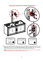
Page 16: ...RACKET against the SPINE D when tightening the bolts with the enclosed hex wrench Make sure the pivoting bolt head faces up NOTE The Spine can provide two height options for the TV set Refer to your TV size and adjust the Swiveling Bracket to the desired height for optimum viewing LOCK WASHER 4 used in this step FLAT WASHER 4 used in this step 5 8 BOLT 4 used in this step ...

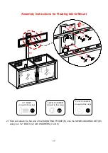
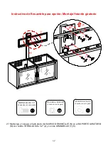
Page 17: ...g Swivel Mount 27 Hold and attach the flat side of the MOUNTING FRAME N onto the SWIVELING BRACKET M using four 1 2 BOLTS 2 with WASHERS 7 and 8 1 2 BOLT 4 used in this step LOCK WASHER 4 used in this step FLAT WASHER 4 used in this step ...

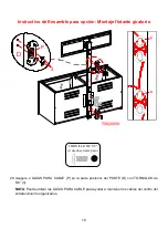
Page 18: ...ting Swivel Mount 28 Attach 2 CABLE WHEELS P onto the backside of the SPINE D with the 5 8 BOLTS 3 NOTE You can use the CABLE WHEELS to help keep the entertainment center s cables and cords organized 5 8 BOLT 4 used in this step P 3 D ...

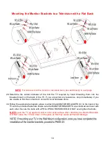
Page 19: ...ediately If you are unable to find the correct bolt consult a local hardware store 30 Follow the appropriate diagram above to attach the MONITOR BRACKETS O to the back of the TV with the selected fasteners Make sure the MONITOR BRACKETS are centered and level with each other Secure the bolts with a PHILLIPS SCREWDRIVER DO NOT over tighten the bolts NOTE Lean the TV up against a wall or other solid...

Page 20: ...rect bolt consult a local hardware store 32 Follow the appropriate diagram above to attach the MONITOR BRACKETS O to the back of the TV with the selected fasteners Make sure the MONITOR BRACKETS are vertically centered and level with each other Secure the bolts with a PHILLIPS SCREWDRIVER DO NOT over tighten the bolts NOTE Lean the TV up against a wall or other solid surface when attaching the Mon...

Page 21: ...r assistance to lift the television up to attach the MONITOR BRACKETS onto the MOUNTING FRAME N Set the hooks on the MONITOR BRACKETS over the MOUNTING FRAME and then lower them onto the bars of the MOUNTING FRAME Loosen the LOCK BOLTS that are pre attached on the MONITOR BRACKETS to ensure an easy fit at the bottom hooks 34 Center the television and tighten both LOCK BOLTS with a long PHILLIPS SC...

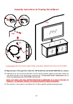
Page 22: ...the console and position it at the desired location against a wall Now follow the instructions printed on the plastic bag containing the TIPPING RESTRAINT HARDWARE KIT to mount the tipping restraint to the SPINE and the wall NOTE YOU MUST USE THIS TIPPING RESTRAINT HARDWARE TO ATTACH THE UNIT TO THE WALL TO PREVENT TIPPING CAUSING ACCIDENTS AND OR INJURIES 37 The console is now ready for use Swive...

Page 23: ...l 3 16 inch diameter holes to at least 2 inch deep on the 4 drill points While holding the Bracket Plate in place loosely screw in the LAG BOLTS 13 40 Secure the MOUNTING FRAME N to wall with LAG BOLTS 13 and WASHERS 14 at the drill points Tighten the bolts firmly but be careful not to over tighten The following steps are only for those who wish to mount their TV directly to the wall If you have a...

Page 24: ...ate mark 4 drill points with a pencil 42 With an electric drill not included on its low setting drill 7 16 inch diameter holes to at least 2 inch deep Insert CONCRETE ANCHORS 12 into the pre drilled holes so that they are flush with the wall 43 Place the MOUNTING FRAME N level in the desired position against the wall Secure the MOUNTING FRAME N to wall with LAG BOLTS 13 and WASHERS 14 at the drill...

Page 25: ...ts over the Mounting Frame and then lower them onto the bars of the MOUNTING FRAME Loosen the lock bolts pre attached on the MONITOR BRACKETS to ensure an easy fit at the bottom hooks Proceed to center the television When the TV is in its intended position tighten both lock bolts with a long Phillips screwdriver until they hit the underside of the MOUNTING FRAME N This will ensure the TV is safely...

Page 26: ...our furniture in a climate controlled environment Extreme temperature and humidity changes can cause fading warping shrinking and splitting of wood It is advised to keep furniture away from direct sunlight as sun may damage the finish Proper care and cleaning at home will extend the life of your purchase Follow these important and helpful tips that will enhance your furniture as it ages A touch up...

Page 27: ...lamente la que se recomienda para la opción que escogio ENSAMBLE REQUERIDO POR ADULTO Si tienen alguna pregunta acerca del ensamble o si alguna parte está faltante no retorne esté producto a la tienda que lo compró Por favor llame a nuestro departamento de ayuda al cliente teniendo su instructivo y lista de partes para proveer el modelo nombre de parte o el número de Fábrica 866 942 5362 Hora Está...

Page 28: ...S CON PANTALLA PLANA DE 55 SIN SOPORTE CON PLACA GIRATORIA MÁXIMA CARGA 135 lb 61 2 kg MÁXIMA CARGA 50 lb 22 6 kg COLOQUE SU TV DETRÁS DEL TOPE ESTA UNIDAD NO DEBE UTILIZARSE CON TELEVISIONES CRT O DE TUBO UTILIZARSE ÚNICAMENTE CON TELEVISIONES DE PANTALLA PLANA Y EQUIPO DE AUDIO VIDEO QUE TENGA LA MEDIDA PESO RECOMENDADO NUNCA UTILIZAR CON TELEVISIONES MÁS GRANDES PESADAS DE LAS RECOMENDADAS PARA...

Page 29: ... antes de iniciar el ensamble A REPISA SUPERIOR 1 B REPISA METÁLICA INFERIOR 1 C REPISA FRONTAL 1 D POSTE 1 E PANEL IZQUIERDO 1 F PANEL DERECHO 1 G PANEL DIVISOR 1 H PANEL INFERIOR 1 I RESPALDO 1 J PUERTA 2 K VIDRIO SUPERIOR 1 L REPISA DE VIDRIO 2 M SOPORTE GIRATORIO 1 N MARCO DE MONTAJE 1 O SOPORTE MONITOR 2 P Guía Para Cable 2 ...

Page 30: ...a 4 TORNILLO DE 1 5 TORNILLO DE 1 1 4 6 TORNILLO DE 2 1 4 7 1 extra 4 1 extra 4 1 extra 7 ARANDELA PRESIÓN 8 ARANDELA PLANA 9 TORNILLO DE 2 22 1 extra 22 1 extra 2 1 extra 10 TORNILLO DE 1 2 11 SOPORTE REPISA 12 ANCLA P CONCRETO 16 1 extra 8 1 extra 4 13 TORNILLO DE 2 1 2 4 14 ARANDELA GRANDE 4 1 extra 15 TOPE ACRILÍCO 1 16 JALADERA C TORNILLOS 2 LLAVE HEXAGONAL 4 MM 2 PLUMÓN DE RETOQUE 1 JUEGO SU...

Page 31: ...de 6x35 mm TORNILLO de 8x16 mm TORNILLO de 8x40 mm 4 4 4 4 ARANDELA CANDADO ARANDELA CANDADO ARANDELA CANDADO ARANDELA CANDADO de 4 mm 4 de 5 mm 4 de 6 mm 4 de 8 mm 4 Espaciador Largo 4 Espaciador Corto 4 Arandela Plana de 4 5 mm 8 Arandela Plana de 6 8 mm 4 Herramienta requerida Llave hexagonal proveida desarmador de cruz no proveidos ...

Page 32: ...a REPISA FRONTAL C usando cuatro TORNILLOS de 1 1 4 5 con ARANDELAS DE PRESIÓN 7 y las ARANDELAS PLANAS 8 Asegúrese de que los soportes de metal en la REPISA SUPERIOR A y los niveladores de piso en la REPISA FRONTAL C apuntan hacia la misma dirección 3 Fije la REPISA METÁLICA INFERIOR B a la REPISA FRONTAL C con las lengüetas de metal hacia arriba Utilice tres TORNILLOS de 1 4 y apriete con la lla...

Page 33: ...n la REPISA SUPERIOR A y luego en los insertos roscados en el PANEL IZQUIERDO E 5 Fije el PANEL IZQUIERDO E a la REPISA METÁLICA INFERIOR B con dos TORNILLOS de 1 4 Apriete los tornillos con la llave Hexagonal suministrada Asegúrese de que no haya espacios entre las PANEL IZQUIERDO E y la REPISA FRONTAL C 6 Repita el mismo procedimiento para fijar el PANEL DERECHO F en el otro lado ARANDELA PLANA ...

Page 34: ...je 7 Usar los pernos de madera como guía alinear y conectar el PANEL DIVISOR G en el PANEL INFERIOR H utilizando dos TORNILLOS de 2 9 Apriete los tornillos con un destornillador estrella 9 H G TORNILLO DE 2 2 usados en este paso ...

Page 35: ... los soportes de metal en el carril medio La REPISA SUPERIOR A en el PANEL DIVISOR G 9 Fije el PANEL INFERIOR H a la REPISA METÁLICA INFERIOR B utilizando seis TORNILLOS de 1 2 10 a través de las lengüetas de metal ARANDELA PLANA 2 usados en este paso ARANDELA PRESIÓN 2 usados en este paso TORNILLO DE 1 2 6 usados en este paso TORNILLO 5 8 2 usados en este paso H G H G ...

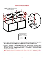
Page 36: ...o 11 Coloque el RESPALDO I a los bordes posteriores del bastidor montado de manera que los agujeros pre perforados para el POSTE D se superponen los agujeros roscados en la REPISA SUPERIOR A Usando los agujeros pre perforados en el RESPALDO I como guía al conectar con los TORNILLOS de 1 2 10 NOTA Se recomienda fijar el RESPALDO con los TORNILLOS de 1 2 en las esquinas primero TORNILLO DE 1 2 10 us...

Page 37: ... E 15 Cierre las puertas para corroborar la alineación Si usted encuentra que las puertas que haya que ajustar un poco por favor consulte el suplemento en la página 2 y gire los tornillos adecuados para una puerta perfectamente alineada Una vez ajustado bloquear las bisagras en su lugar apretando el perno de la bisagra en la base 16 Quite la JALADERA C TORNILLOS 16 y luego utilice los tornillos pa...

Page 38: ...bajo sobre las VENTOSAS 1 Asegúrese de que el VIDRIO está correctamente centrado NOTA Si el VIDRIO se raya se puede minimizar el daño mediante el uso de un marcador NEGRO y rellenando el área rayada por debajo 19 Inserte los SOPORTES REPISA 11 en los orificios deseados en los PANELES LATERALES E y F y PANEL DIVISOR G Asegúrese de colocar el estante de cuatro soportes en el mismo nivel por lo que l...

Page 39: ...cesario ajuste los niveladores de piso pre conectados en la parte inferior de la REPISA FRONTAL C para nivelar la unidad 21 Retire la cinta del TOPE DE ACRÍLICO 15 y colóquela en la muesca de la PLANTILLA DEL TAPÓN DE ACRÍLICO de la parte frontal del VIDRIO SUPERIOR K Asegúrese de que está correctamente alineado antes de aplicar presión 22 Retire la plantilla TOPE DE ACRÍLICO cuidadosamente TOPE A...

Page 40: ...na pared A continuación siga las instrucciones que se encuentran en la bolsa de plástico con el Juego Sujetador hacia el POSTE NOTA DEBE UTILIZAR ESTE JUEGO SUJETADOR PARA ASEGURAR LA UNIDAD A LA PARED PARA PREVENIR ACCIDENTES O DAÑOS 24 La Consola está lista para usarse Colóquela frente a la pared en el lugar deseado y posicione su Televisión encima cerciorandose de que esté centrada NOTA Para mo...

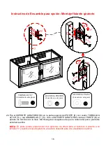
Page 41: ...ANDELAS 7 y 8 Apriete los tornillos con la llave Hexagonal Asegúrese de que los agujeros roscados para la guía de cable P apuntan hacia atrás Instrucciones de Ensamble para Montaje flotante giratorio ARANDELA PRESIÓN 4 usados en este paso ARANDELA PLANA 4 usados en este paso Tornillo de 2 1 4 4 usados en este paso ...

Page 42: ... el POSTE D al apretar los tornillos con la llave M4 Hexagonal Asegúrese de que la cabeza del perno pivotante esta hacia arriba NOTA El poste puede proporcionar dos opciones de altura para el televisor Consulte a su tamaño TV y ajuste el soporte giratorio a la altura deseada para una visualización óptima ARANDELA PRESIÓN 4 usados en este paso ARANDELA PLANA 4 usados en este paso TORNILLO 5 8 4 usa...

Page 43: ...atorio 27 Mantenga y coloque el lado plano del MARCO D EMONTAJE N en el SOPORTE GIRATORIO M con cuatro TORNILLOS de 1 2 2 y con las ARANDELAS 7 y 8 TORNILLO DE 1 2 4 usados en este paso ARANDELA PRESIÓN 4 usados en este paso ARANDELA PLANA 4 usados en este paso ...

Page 44: ...iratorio 28 Asegure 2 GUÍAS PARA CABLE P en la parte posterior del POSTE D con TORNILLOS de 5 8 3 NOTA Puede utilizar las GUÍAS PARA CABLE para ayudar a mantener los cables del centro del entretenimiento organizados P 3 D TORNILLO DE 5 8 4 usados en este paso ...

Page 45: ...nte Si no encuentra el tornillo adecuado dirígase a su tienda de ferretera local para el mismo 30 Cuando determine el diámetro correcto del tornillo a utilizar siga el diagrama apropiado de abajo asegure el tornillo corto y arandelas junto con el SOPORTE DE MONITOR O en las inserciones roscadas que están en la parte superior de la Televisión NOTA Recarge la TV contra la pared u otra parte sólida c...

Page 46: ...rígase a su tienda de ferretera local para el mismo 32 Cuando determine el diámetro correcto del tornillo a utilizar siga el diagrama apropiado de abajo asegure el tornillo corto y arandelas junto con el SOPORTE DE MONITOR O en las inserciones roscadas que están en la parte superior de la Televisión NOTA Recarge la TV contra la pared u otra parte sólida cuando asegure los SOPORTES de MONITOR POR N...

Page 47: ...ORTES del MONITOR O estén atornillados pida ayuda para colgar la televisión en el MARCO de MONTAJE N Coloque los ganchos del Soporte sobre el marco y centre la televisión Afloje los TORNILLOs candado pre ensamblados en los SOPORTES del MONITOR para que entre fácilmente el gancho 34 Una vez que la TV este en su lugar asegure ambos candados con los TORNILLOS FIJADORES utilizar un Desarmador estrella...

Page 48: ...a la consola y colocarla en la posición deseada en la pared Ahora siga las instrucciones impresas en la bolsa de plástico que contiene el JUEGO SISTEMA DE SEGURIDAD para montar el sistema de seguridad de vuelco de la columna vertebral y la pared NOTA DEBE USAR ESTE SISTEMA DE SEGURIDAD PARA COLOCAR LA UNIDAD EN LA PARED PARA EVITAR VUELCO causando accidentes y o lesiones 37 La consola está ahora l...

Page 49: ...de dibujar 39 Con un taladro eléctrico no incluido taladre unos agujeros de 3 16 de diámetro de por lo menos 2 pulgada de profundidad en los cuatro puntos de perforación Mientras se mantiene la placa de soporte en su lugar sin apretar el TORNILLO LARGO 13 40 Asegurar el MARCO de MONTAJE N a la pared con los TORNILLOS LARGOS 13 y ARANDELAS 14 en los puntos de perforación Apriete los tornillos con f...

Page 50: ...untos para taladrar 42 Con un taladro eléctrico el cual no está incluido en su menor fuerza de ajuste taladre agujeros de 7 16 11 mm de diámetro a por lo menos 6 35 cm de profundidad Inserte los TAQUETE para CONCRETO 12 en los agujeros taladrados anteriormente hasta que estén al ras con la pared 43 Coloque el MARCO de MONTAJE N en la posición que desee contra la pared Asegúrelo a la pared con los ...

Page 51: ...y luego bajarlos a las barras del bastidor de montaje Afloje los tornillos de fijación de pre conectados en los soportes de monitor para asegurar un ajuste fácil en los ganchos inferiores Seguir en el centro de la televisión Cuando el televisor está en su posición deseada apriete los dos tornillos de fijación con un destornillador Phillips largo hasta que lleguen a la parte inferior del MARCO DE M...

Page 52: ...n causar cambios como partes pandas molduras que se contraigan o que la madera se raje Es recommendable mantener la unidad lejos del sol directo ya que puede dañar el terminado Cuidados adecuados y limpieza pueden extender la vida útil de su unidad Siga estás recomendaciones y mantendra su mueble en buenas condiciones de uso por muchos años Un plumón de retoque se incluyó para reparar cualquier pe...

Reviews: