Description
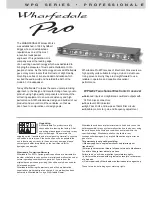
The WPG - 202 Series of Electronic crossovers fit
,,
standard 1U, 19 (482mm) racks. The WPG crossovers
are housed in steel cases suitable for racking in
professional flight cases.
Operating
I) When switching on the Electronic crossovers ensure
that all audio inputs are connected and that the mains
connections are safely and securely connected at the
supply and unit. All internal servicing must be referred
to qualified service personnel with access to technical
documentation but if the unit fails to work the user can
apply a few basic checks to locate possible problems.
I) If the Power LED is not on:
There is no mains power to the unit.
Check mains connections thoroughly. Check fuses.
Ii) If a system has been set up, and the crossover is
thought not to be functioning, please check the system
connections. If however, the system has already been
working perfectly and the crossover is suspect, follow
the basic fault finding procedure given above. If this
does not produce any results, contact your dealer, who
will be able to solve the problem quickly. Most
malfunctions can be traced to cable (input, output and
mains) failure or to the connections.
Connections
Each input channel is electronically balanced with
female XLR connectors.
In accordance with IEC and AES/ANSI standards the
wiring mode is Pin 1 Earth (signal ground), Pin 2
,,
(positive) and Pin 3 Cold (negative, return). The1/4
Jack socket is also wired in parallel with the XLR. The
Tip is Hot, the ring is Cold and the Sleeve is Ground.
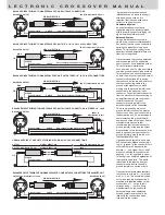
Balanced Operation:
Use only when driving from a
t
rue balanced source
and driving to a
true balanced
destination.
Either transformer balanced or with active
drive. Connect the input between pins 2 and 3 with pin
2 positive. Do not connect pin 1. Attached the shield to
connector case (chassis ground). Connect the output
between pins 2 and 3 with pin 2 positive. Do not
connect pin 1.
Do not
connect the shield at this end to
anything.
Unbalanced Operation:
Connect the input between
pins 2 and 1 with pin 2 positive and pin 1 earth (signal
ground). Short pin 3 to pin 1. Attach the shield to
connector case (chassis ground). Connect the output
between pins 2 and 1 with pin 2 positive. Leave pin 3
open -
Do not
short it to pin 1.
Do not
connect the
shield at this end to anything.
Operation
The WPG-202 Series of Electronic crossovers can be
used as a 2 way stereo crossover or a mono 3 way
crossover.
The unit comes in the signal chain before the power
amplifier and after the source (mixer, disco equipment
etc.) and other units such as graphic equalisers or
other equaliser units.
Using the WPG-202 Series of Electronic as a 2 way
stereo crossover
In the stereo mode the switch (12) in the picture would
,
,
be in the out position. The stereo signals should be
inserted at the rear of the unit into channel one and
channel two. The outputs (high and low) would go to
the power amplifier. There are clear legends on the rear
panel showing these input and outputs for the two
operating modes (mono and stereo). To operate set the
input level on channel 1 (left) so that the signal peak
indicator is not flashing constantly (the LED may flash
occasionally but this does not necessarily mean an
overload is occurring). Set the crossover frequency
low/(mid)high control (8) and adjust the low level output
(7) and high level output (10) to the desired levels (see
,
,
below
Selecting the right crossover frequencies
).
Follow the same procedure for channel two
remembering that the controls of channel one are the
same as channel two when in Stereo mode. For this
,
,
mode the x1/x10 switch (9) may be need to be in to
enable a higher crossover point to be used
,
(see
,
).
Using the WPG-202 Series of Electronic as a 3 way
mono crossover
In the stereo mode the switch (12) in the picture should
,
,
be in the in position. The mono signal should be
inserted at the rear of the unit into channel one only.
The 3 outputs (high, mid and low) should go to the
power amplifier(s). There are clear legends on the rear
showing these input and outputs for the two operating
modes (mono and stereo). To operate set the input
level on channel 1 (left) so that the signal peak
indicator is not flashing constantly (the LED may flash
occasionally but this does not necessarily mean an
overload is occurring). Set the crossover frequency for
low/mid control (8) and adjust the low level output (7)
and mid level output (10) to the desired output levels
,
(see below
Selecting the right crossover
,
frequencies
). Select via control no.15 the crossover
point between mid and high and adjust control no.14 for
the high output level.
For this the mono mode switch (16) may be need to be
,
,
in to enable a higher crossover point (see below
W P G
S E R I E S
P R O F E S S I O N A L
E


