background image

4000x Series Digital Clock 

Operating and Installation Instructions


Installation and Operation 

Power Supply Connection 

The 4000x series digital clocks are fi ed with either universal mains power supplies (enabling opera on at 

voltages from 100 to 240V AC 50/60Hz without adjustment), low voltage DC power supplies or 

Power-over-Ethernet (PoE) power supplies, as specified at  me of order. 
Units are supplied with a 2m mains cable preterminated with a UK style moulded plug (units for supply to 

the USA or Canada are supplied with a 2m cap ve mains cable preterminated with a US style moulded 

plug). 

A connection to the earth line must be made to ensure safe operation and  

compliance with EMC regulations. 

To ensure conformance with EN60950: 

A.

For installa ons where the 4000x series digital clock is to be permanently connected into the 

mains power circuit, a readily accessible disconnect device should be incorporated in the fixed 

wiring. 

B.

For installa ons where the 4000x series digital clock is to be plugged into the mains power 

circuit, a socketed outlet should be installed near the equipment and should be easily 

accessible. 

All installa on work should be performed in accordance with current Building Regula ons and the 

Seventeenth Edi on of the IEE Wiring Regula ons, or equivalent local standard. 
The power supply is fi ed with an internal fuse. In case of fault the fuse should only be replaced with a fuse 

of the same ra ng, by a suitably qualified engineer a er disconnec on from the mains power supply and 

correc on of the fault condi on. 

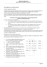
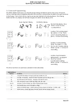
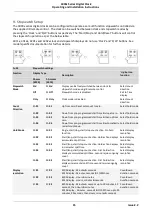
Remote Control and Rear Switches 

In addi on to the rear se ng switches, the 4000x series digital clock displays are supplied with an Infrared 

Remote Control to allow for easy se ng of the unit. 
 

‘Up’ - Used to navigate up through se ng menus or 

access Func on Menu when  me is displayed. 

‘+’ -  Used to increment se ng op ons. 

‘-’ - Used to decrement se ng op ons. 

‘Down’ - Used to navigate down through se ng 

menus. 

‘Menu’ - Used to access Func on Menu on clock. 

‘Exit’ - Used to exit from any clock se ng menu to 

normal clock display. 

‘Start/Stop’ - Only used in Stopwatch Mode.  See 

Sec on 9 for further informa on 

‘Hold/Reset’ - Only used in Stopwatch Mode.  See 

Sec on 9 for further informa on. 

‘Clock Mode’ - Used to place clock into Clock Mode. 

See Sec on 9 for further informa on. 

10  ‘Stopwatch Mode’ - Used to display Stopwatch Mode. 

See Sec on 9 for further informa on 


4

 Issue 2.2 

Summary of Contents for 4000x Series

Page 1: ...hronisa on Setup Page 9 7 Network Setup Page 12 8a Display Setup 4200x and 4010x series Page 13 8b Calendar Setup 4500x and 4600x series Page 14 9 Stopwatch Setup Page 15 10 External Interface Setup P...

Page 2: ...the limits for a Class B digital device pursuant to Part 15 of the FCC Rules These limits are designed to provide reasonable protec on against harmful interference in a residen al installa on The equ...

Page 3: ...sor All of the digital clocks also have the ability to operate as a mul range programmable stopwatch using supplied infrared remote control or for 4000NE and 4000E units only using an external stopwat...

Page 4: ...ould be easily accessible All installa on work should be performed in accordance with current Building Regula ons and the Seventeenth Edi on of the IEE Wiring Regula ons or equivalent local standard T...

Page 5: ...t se ng Func on Loca on Se ng Mode See page 5 1 Press Up to enter Loca on Se ng Mode or press to move to next se ng Func on Synchronisa on Se ng Mode See page 6 1 Press Up to enter Synchronisa on Se n...

Page 6: ...Up to set minutes count Minutes Se ng Mode Press or to increment or decrement minutes Press Up to set the hours count Complete me se ng process detailed in table below Fu Ti Time and Date settings Fu...

Page 7: ...ST MEZ MESZ Brussels Frankfurt 1 Yes 04 UTC 2 BRAVO SAST Jo burg Pretoria S Africa 2 No 05 EET EEST Greece Athens Ukraine Kiev 2 Yes 06 IST IDT Israel Tel Aviv 2 Yes 07 MSK 1 Russia Kaliningrad 3 No 0...

Page 8: ...n na Buenos Aires 3 No 63 BRT BRST Brazil Brasilia Sao Paulo 3 Yes 64 WGT WGST Greenland West Nuuk 3 Yes 65 PMST PMDT US Pierre Miquelon 3 Yes 66 UYT UYST Uruguay Montevideo 3 Yes 67 UTC 2 5 2 1 2 No...

Page 9: ...s DHCP server User se ng of NTP server addresses Exit to Time display dh No dh No Sta c assignment of IP Subnet and Gateway addresses by user User se ng of NTP server addresses Select IP Byte 1 IP Byt...

Page 10: ...2 Time code from exis ng 5200 4860 or 482D series master clock Y Y Y Zo 1 F w482 me code zone that unit will use for synchronisa on DCF DCF77 Radio me code synchronisa on requires 484 03 radio receive...

Page 11: ...d the Up arrow should be pressed again to return to the me display If clock is to DHCP or Sta c modes the 4 bytes of the rst NTP me server address can be programmed in same manner as detailed for the...

Page 12: ...to DCF or MSF radio me code when connected to either the 484 02 MSF Radio Receiver or 484 03 DCF Radio Receiver supplied separately as follows Clock configuration 1 Press Menu or Up bu on to access c...

Page 13: ...me date and con nuous date in a number of di erent display formats as detailed in the table below Fu Di Display Setup Function Display Type Description Up button function hh mm 4200 hh mm ss 4010 Disp...

Page 14: ...language table below Calendar 2 Mode Calendar 2 Mode M2 xx As mode se ngs for Calendar 1 above Calendar 2 Lang Calendar 2 Language C2 xx Calendar 2 Language as per language table below Calendar 3 Mod...

Page 15: ...ect hold mode SA 03 SA 03 Down from pre programmed start me then up from zero Select hold mode SA 04 SA 04 Down from pre programmed start me automa cally restart countdown Select hold mode Hold Mode S...

Page 16: ...n provide synchronisa on to a maximum 5 4000E units See Local Master documenta on for further details Exit to me display 11 System setup The system setup menu contains general setup op ons for the 400...

Reviews: