page 8 – 5
A-5000 / Nov 98
S U P E R P H O N E I N P U T
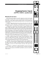
Drop Caller LED Inputs
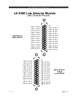
The DROP CALLER switch’s internal LED’s are accessible from the module’s
LDB-25 connector and can be wired as Active Caller tallies from your external
hybrid. When a line is answered on the hybrid, the Tally for that line can light the
corresponding DROP1 or DROP 2 LED. Note that the DROP LED com (anode, LDB
Pin 5) requires a +5V input. DROP LED 1 (LDB Pin 1) and DROP LED 2 (LDB Pin
14) are connected to the LED’s cathodes and require open collector to GND signals.
Typical Answer Call Sequence
1. Phone line rings.
2. DJ presses ANSWER CALLER 1 switch on SPN-5000.
3. a) Momentary opto closure at ANSWER CALLER 1 output picks up
phone line on hybrid
b) Caller’s voice is routed to A-5000 console CUE speaker
c) Pre fader on DJ mic is routed to caller
d) DROP 1 LED on SPN-5000 module is lit from the hybrid’s Tally output.
To Drop Caller
1. DJ presses DROP 1 Button
2. a) Momentary opto closure at DROP 1 output disconnects the caller from the
hybrid
b) DROP 1 LED goes out
c) CALLER 1 audio input is dropped from the CUE bus (provided the
corresponding Cue Dropout Dipswitch SW2-4 for CALLER 1 or
SW3-4 for CALLER 2 is ON).


