page 8 – 8
A-5000 / Nov 98
S U P E R P H O N E I N P U T
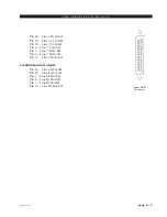
Typical DB-25
connector
When the module’s ON/START switch is pressed, a closure takes place
between start/stop common and START; when the module’s OFF switch is
pressed, a closure takes place between start/stop common and STOP. These
may be used to control a remote tape machine for recording phone segments.
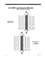
Audio and Control Connections (lower DB-25)
These include outputs to the station hybrid, module output composite
feeds (for recording), drop caller and answer caller connections.
Pin 25 – Composite Out SH
Pin 24 – Composite Out HI
Pin 12 – Composite Out LO
Pin 11 – Composite Minus Callers Out SH
Pin 10 – Composite Minus Callers Out HI
Pin 23 – Composite Minus Callers Out LO
Pin 22 – Callers Only Out SH
Pin 21 – Callers Only Out HI
Pin 9 – Callers Only Out LO
Pin 8 – To Hybrid 1 Out SH
Pin 7 – To Hybrid 1 Out HI
Pin 20 – To Hybrid 1 Out LO
Pin 19 – To Hybrid 2 Out SH
Pin 18 – To Hybrid 2 Out HI
Pin 6 – To Hybrid 2 Out LO
Pin 5 – Drop LED Common
Pin 17 – Drop Common
Pin 16 – Drop Caller 2
Pin 15 – Drop Caller 1
Pin 14 – Drop Caller 2 LED
Pin 1 – Drop Caller 1 LED
Pin 4 – Answer Common
Pin 3 – Answer Caller 2
Pin 2 – Answer Caller 1


