page 2 – 8
A-7000 / Sep 2002
M O N O M I C / L I N E I N P U T M O D U L E
Timer Restart
When the module is turned ON the console’s digital timer can be
programmed to automatically reset to zero and being counting up.
SW15 Position 3 activates Timer Restart when mic A is turned ON
SW16 Position 7 activates Timer Restart when mic B is turned ON
Phantom Power
Positions 1 and 2 of seven-position dipswitch SW6 turn phantom
power on (UP position) and off (DOWN position). Position 1 controls
microphone input A, and position 2 microphone B.
Hook-Ups
As stated before, all user wiring to and from ML-7000 modules is
done via two DB-25 multi-pin connectors located in the bottom of the
console’s mainframe, directly underneath each individual module, and
one DB-9 connector mounted on the console’s motherboard. A pinout
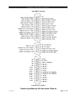
drawing on page 2-11 shows all wiring connections at a glance.
Audio Connections
Upper DB-25 Connector
These include A and B mic/line inputs, and insert in and out. The mic
input level is nominally -50dBu, line input and in/out insert points level
are +4dBu balanced. All signals are analog mono.
Pin 25 – Mic A In SH
Pin 24 – Mic A In HI
Pin 12 – Mic A In LO
Pin 11 – Mic B In SH
Pin 10 – Mic B In HI
Pin 23 – Mic B In LO
Pin 19 – Line A In SH
Pin 18 – Line A In HI
Pin 6 – Line A In LO
Pin 5 – Line B In SH
Pin 4 – Line B In HI
Pin 17 – Line B In LO
Pin 16 – Insert Out SH
Pin 15 – Insert Out HI
Pin 3 – Insert Out LO
Pin 2 – Insert In SH
Pin 1 – Insert In HI
Pin 14 – Insert In LO
Note the insert points are normally bypassed by PCB-mounted slide
SW17 (see page 2-6).
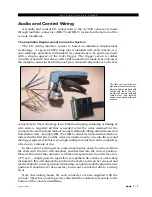
Typical DB-25
connector
Note the factory default
setting for phantom power
is OFF.

