page Contents – 2
A-7000 / Sep 2002
C O N T E N T S
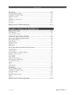
Hook-ups ........................................................................................ 2-8
AUDIO CONNECTIONS ........................................................................................... 2-8
CONTROL CONNECTIONS ..................................................................................... 2-9
ON & OFF Switch ..................................................................................................... 2-9
Cough ....................................................................................................................... 2-9
Talkback to Control Room ....................................................................................... 2-10
On Tally .................................................................................................................... 2-10
Off Tally .................................................................................................................... 2-10
DB Connector Pinout Drawing .................................................... 2-11
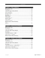
Chapter 3 - Stereo Line Input Module
Module Overview ........................................................................... 3-2
Flow Diagram ............................................................................................................ 3-2
Controls and Functions ............................................................................................. 3-3
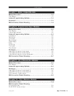
Internal Programming Options .................................................... 3-5
Stereo Input Signal Routing Switches ................................................................. 3-5
Music/Speech Assign ............................................................................................... 3-5
Insert Bypass ............................................................................................................ 3-5
Mix-Minus Assign ...................................................................................................... 3-6
Send Mode ................................................................................................................ 3-6
IFB Assign ................................................................................................................. 3-6
Stereo Input Switch Controlled Logic Functions ................................................ 3-6
Auxiliary Assign ........................................................................................................ 3-6
Utility Assign ............................................................................................................. 3-6
Remote ON/OFF - Start/Stop Disable ...................................................................... 3-6
External - Pulse/Constant ......................................................................................... 3-7
Send Assign .............................................................................................................. 3-7
Mono Assign ............................................................................................................. 3-7
CUE and Solo Dropout ............................................................................................. 3-7
EFS (European Fader Start) ..................................................................................... 3-7
Local Ready Function ............................................................................................... 3-7
Mutes ........................................................................................................................ 3-7
Tally .......................................................................................................................... 3-8
Timer Restart ............................................................................................................ 3-8
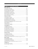
Hook-ups ........................................................................................ 3-8
AUDIO CONNECTIONS ........................................................................................... 3-8
CONTROL CONNECTIONS ..................................................................................... 3-9
ON & OFF Switch .................................................................................................... 3-10
On Tally .................................................................................................................... 3-10
External START & STOP ........................................................................................ 3-10
Ready ....................................................................................................................... 3-11
DB Connector Pinout Drawing .................................................... 3-12


