page 5 – 3
A-7000 / Sep 2002
C O N T R O L R O O M M O D U L E
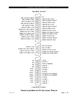
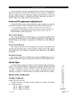
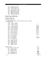
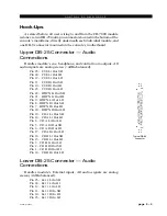
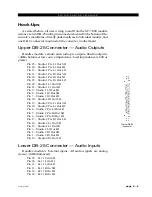
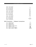
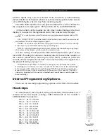
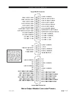
All user wiring to and from the CR-7000 module is done via two DB-
25 multi-pin connectors located in the bottom of the console’s mainframe,
directly underneath the module, and one DB-9 connector mounted on the
console’s motherboard. A pinout drawing on page 5-7 shows all wiring
connections at a glance.
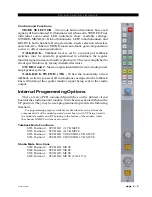
Controls and Functions
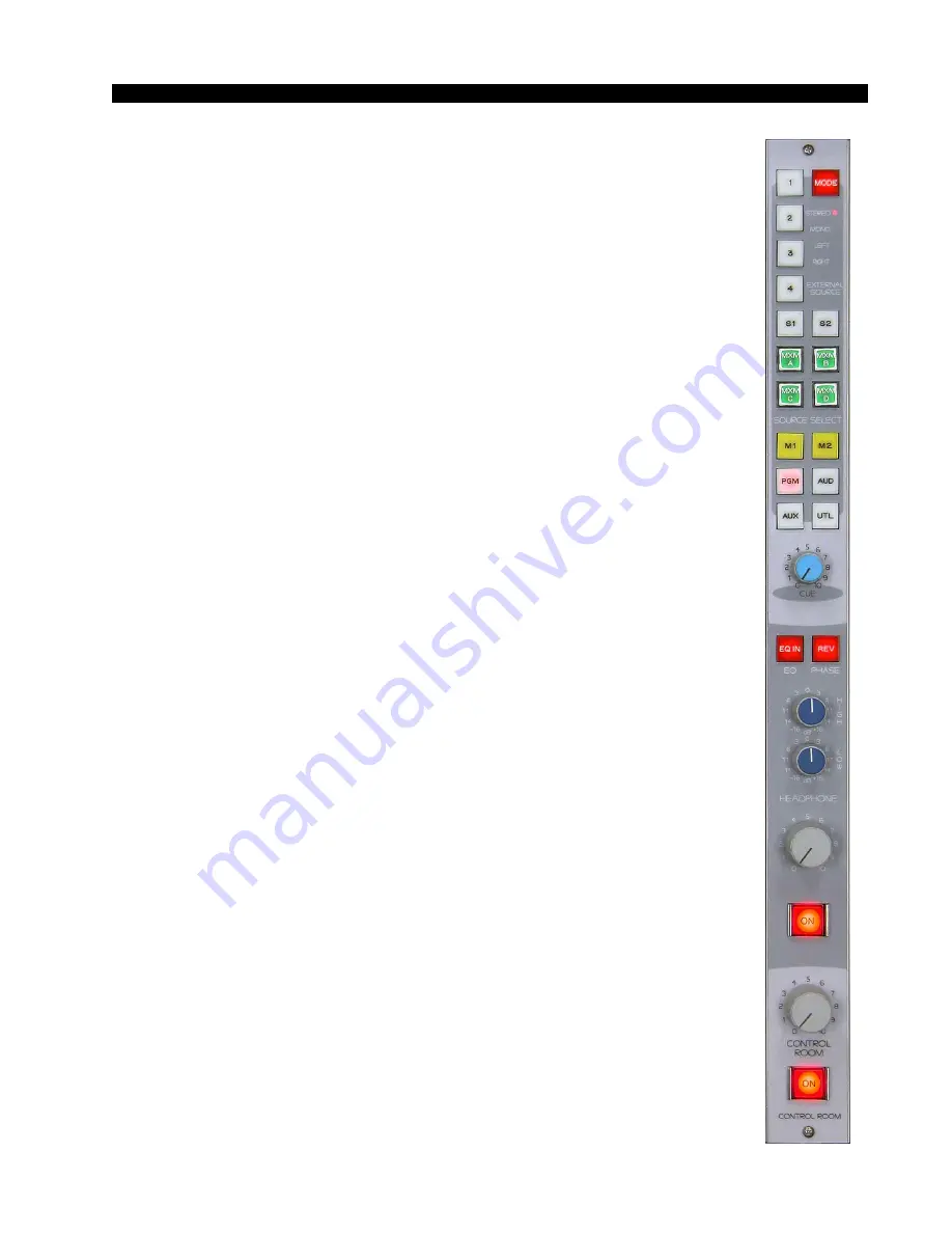
MODE SELECTOR – The mode button determines how each signal
will be monitored. It illuminates red when set to STEREO. Four individual
color-coded LED indicators show available settings: STEREO, MONO
(L+R to both channels), LEFT to both channels, and RIGHT to both
channels. Being electronic, mode selection is lossless and click-free.
When in MONO mode automatic gain compensation occurs to offset
mono summation.
CUE – This is the master level control for the console's CUE/SOLO
signals. Whenever a Cue or Solo button is pushed anywhere on the
console, the resulting signal automatically interrupts the regular monitor
program source. Exactly what form this interruption takes is program-
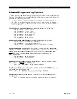
mable via PCB-mounted dipswitches. Note Cue/Solo signals also appear
at the console's built-in stereo cue speakers (mounted left and right in the
VU meterbridge) via a built-in power amplifier.
HEADPHONE – The built-in headphone circuit includes an on/off
switch, a level control, high and low EQ (continuously variable,
±
16dB,
with EQ in/out switch) and a unique phase switch (REV), which reverses
the phase of both the left and right channels to optimize audio clarity for
the announcer's voice by putting the headphone audio in phase with his
own internal auditory path. Note that Headphone normally listens to the
same source as the control room but automatically switches to Cue or Solo
when so selected (this feature may be internally defeated by dipswitch).
External headphone jacks are provided on the left and right sides of the
console mainframe (just below counter height, to keep cords away from
the work surface).
CONTROL ROOM – A conductive plastic level pot (with on/off
switch) controls CR monitor signals.


