page 6 – 3
A-7000 / Sep 2002
S T U D I O C O N T R O L M O D U L E
Controls and Functions
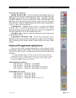
MODE SELECTOR – The mode button determines how each
signal will be monitored. It illuminates red when set to STEREO. Four
individual color-coded LED indicators show available settings:
STEREO, MONO (L+R to both channels), LEFT to both channels, and
RIGHT to both channels. Being electronic, mode selection is lossless
and click-free. When in MONO mode automatic gain compensation
occurs to offset mono summation.
TALKBACK – Talkback level is set by a control pot; talkback
switches may be specially programmed to attentuate the regular
monitor signal (instead of totally replacing it). This is accomplished to
client specifications by factory-installed resistors.
STUDIO 1and 2 – Stereo outputs intended for remote studio power
amp/speaker systems.
TALKBACK SWITCH (TB) – When the momentary action
talkback switch is pressed, all microphones assigned to the talkback
bus will interrupt the regular monitor signal being sent to the studio
output.
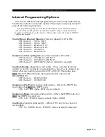
Internal Programming Options
There are two PCB-mounted dipswitches on the printed circuit
board of the studio monitor module. Switches are activated when in the
UP position. They may be user-programmed to provide the following
functions.
For programming purposes switches are described as viewed from the
component side of the module printed circuit board, with UP being towards
the module faceplate and RT pointing to the bottom of the module, where
the channel ON/OFF switches are located.
Talkback Mute Functions
SW3 Position 4 – STUDIO 1 (3) TB MUTE
SW3 Position 3 – STUDIO 2 (4) TB MUTE
SW3 Position 2 – STUDIO 1 TO STUDIO 2 TB MUTE
SW3 Position 1 – STUDIO 2 TO STUDIO 1 TB MUTE
Studio Mute Functions
SW4 Position 4 – STUDIO 1 MUTE
SW4 Position 3 – STUDIO 2 MUTE
SW4 Position 2 – STUDIO 3 MUTE
SW4 Position 1 – STUDIO 4 MUTE (TALLY 3)


