page 8 – 6
A-7000 / Sep 2002
S U P E R P H O N E I N P U T
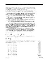
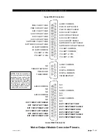
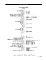
Lower DB-25—Control Connections
These are simply two parallel-connected sets of pins for the same
control port.
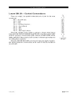
Pin 1 – Record Ready
Pin 2 – Start
Pin 3 – Stop
Pin 4 – Start/Stop Common
Pin 14 – Record Ready
Pin 15 – Start
Pin 16 – Stop
Pin 17 – Start/Stop Common
When the module’s ON switch is pressed, a closure takes places
between START/STOP COMMON and START; when the module’s OFF
switch is pressed, a closure takes place between START/STOP COM-
MON and STOP. These may be used to control a remote tape machine for
recording phone segments.
When the RECORD READY switch is activated, pressing the module’s
ON button generates a closure that can be used to start the machine in
record mode.
Typical DB-25
connector


