background image

page  4 – 19

2001 / Oct 02

X P O I N T   S O F T W A R E   S E T U P   G U I D E

Signal Locking

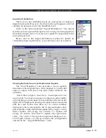
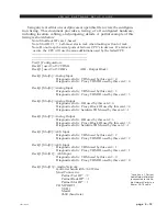
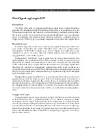
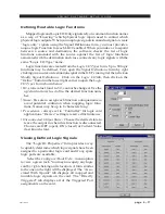
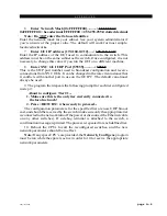
To lock a signal, right  click on one of available output channels on the

crosspoint grid and select “Lock Connection”:

That crosspoint output signal becomes locked as indicated by red line through

the signal on the GUI display and shown on form below:

Summary of Contents for Bridge 2001

Page 1: ...Bridge 2001 Digital Audio Network Router T echnical Manual Wheatstone Corporation July 2001 ...

Page 2: ... 638 7000 fax 252 637 1285 Bridge 2001 Digital Audio Network Router Bridge 2001 Digital Audio Network Router Bridge 2001 Digital Audio Network Router Bridge 2001 Digital Audio Network Router Bridge 2001 Digital Audio Network Router 2001 Wheatstone Corporation ...

Page 3: ...domestic environment This is Class A product In a domestic environment This is Class A product In a domestic environment This is Class A product In a domestic environment This is Class A product In a domestic environment this product may cause radio interference in which case this product may cause radio interference in which case this product may cause radio interference in which case this produc...

Page 4: ...Connections SPDIF 1 7 Chapter 2 Hardware Chassis Backplane Overview 2 4 Chassis Configuration Guidelines 2 5 Audio Slots 2 5 Reserved Slots 2 5 Backplane Termination 2 5 Digital Input Card AES 2024 Overview 2 6 AES Input Interface 2 6 Internal Programming Options 2 6 Status LED s 2 7 Hook Ups DB 25 Digital Audio Connections 2 8 2DB 25 Digital Audio Connections 2 8 8 BNC Digital Audio Connections 2...

Page 5: ...l Programming Options 2 20 Status LED s 2 21 Hook Ups DB 25 Digital Audio Connections 2 22 8 BNC Digital Audio Connections 2 22 8 RJ 45 Digital Audio Connections 2 23 DB Panel Pinout Drawing 2 24 8 BNC Panel Pinout Drawing 2 25 8 RJ Panel Pinout Drawing 2 26 Analog Output Card AO 2001 Overview 2 27 Analog Output Interface 2 27 Internal Programming Options 2 27 Status LED s 2 28 Hook Ups Upper DB 2...

Page 6: ...onnections 2 38 RJ 45 Ethernet Connections 2 38 Typical Ethernet Cable 2 39 Typical Crossover Cable 2 39 PWIH Panel Pinout Drawing 2 40 Audio Network Card OAN 2001 Overview 2 41 Internal Programming Options 2 42 Switch Settings 2 42 DIPSW1 SW4 485 Termination 2 42 DIPSW5 position Local Remote Clock Sources 2 43 DIPSW5 position Secondary Primary 2 43 DIPSW5 position 48 kHz 44 1 kHz 2 43 DIPSW5 posi...

Page 7: ...Ups 2 54 Logic I O Card LIO 2001 Overview 2 55 Input Ports 2 55 Output Ports 2 56 Typical Input Output Circuit 2 56 Software Programming 2 57 Internal Programming Options 2 57 Jumper Dipswitch Settings 2 57 Status LED s 2 58 Hook Ups 2 59 Upper A DB 25 Logic In Ports Connections 2 59 Lower B DB 25 Logic Out Ports Connections 2 59 LIO Panel Pinout Drawing 2 61 Quad Audio Network Card QAT 2001 Overv...

Page 8: ...rawing 2 70 QOT Panel Pinout Drawing 2 71 Digital Signal Processor Card DSP 2001 Overview 2 72 Internal Programming Options 2 72 Switch Settings 2 73 SW1 DSP Reset Switch 2 73 Jumper Settings 2 73 J1 Factory Use Only Watchdog Reset 2 73 J2 Factory Use Only Watchdog Reset 2 73 J3 Factory Use Only Watchdog Disable 2 73 Status LED s 2 74 Microphone Card MIC 2001 Overview 2 75 Analog Input Interface 2...

Page 9: ...ons 3 7 Console RS 485 Cable Pinouts 3 7 Console CPU Module Settings 3 8 Console Address 3 8 RS 485 Select Termination 3 8 Chapter 4 XPoint Software Setup Guide Bridge 2001 Ethernet IP Address Quick Start 4 2a Ethernet Cabling 4 2a Default IP Address 4 2a Changing your PC s IP Address 4 2a Changing the Bridge 2001 s IP Address 4 2a Configuring IP Address in X Point Software 4 2b Saving the Bridge ...

Page 10: ... Signal Definitions 4 16 Defining Routable Logic Functions 4 17 Viewing Defined Logic Signals 4 17 Configuring Triggered Port Logic 4 18 Signal Locking 4 19 Salvo Definition 4 20 XY Rack or Console XY Controller Configuration 4 21 Console Configuration 4 22 Special Functions Console Locks 4 22 Console Presets 4 22 XY GUI Controller Configuration 4 23 Main Menu Summary 4 24 Glossary Terminology G 1...

Page 11: ...troduction 1 2 Power Supply 1 3 Power Supply Cable Pinout 1 3 Failsafe Dual Redundant Supply 1 4 Energizing 1 4 I O Connections 1 5 The Insulation Displacement Connector System 1 5 Digital Audio Connections 1 6 Unbalanced Analog Connections 1 6 Unbalanced Digital Connections SPDIF 1 7 2001 Aug 03 ...

Page 12: ... channels Systems can start small with a single cage and only a few cards chassis can be stacked to form a larger central system Cages can be separated by very long distances with many studios connected to your central rack room providing shared resources yet still permitting independently functioning satellite studios each with its own combination of analog and digital input and output cards and ...

Page 13: ...PS 400 unit the power supply cable plugs into the power supply con nector located on the rear PWIH PWI 2001 module in the ex treme left hand slot looking at the rear of the chassis If you are using twosupplies failsafeoption onesup ply will connect to each 2001 connec tor otherwise only one connector will be used it does not matter which one When the 2001 is powered by the SPS 40 unit there is an ...

Page 14: ...der for failsafe systems to perform as designed always have BOTH rackmount supplies powered up and connected to their associ ated equipment Energizing Assuming the 2001 and its PSR power supply are correctly rackmounted youmaynowenergizethePSRrackmountpowersupply by plugging it into the AC mains Note To de energize the 2001 unplug the rackmount power supply s AC cord from the AC mains Never de ene...

Page 15: ... multipin connector held in the tool s jaw automatically indexes to the next connector pin The technology is such that no stripping soldering or tinning of wire ends is required all that is needed is for the wires destined for the connector be snub cut and laid out in order although tubing should be used on bare drain wires An empty DB 25 or DB 9 connector is inserted into the tool indexed to the ...

Page 16: ...ied DB 25 male mating connectors These crimp style connectors are the insulation displacement type and will accept wire gauge24 22AWG Ifanoptionalrearpanelconnectortype e g BNC RJ 45 etc was specified and shipped with your system please refer to the mating connector manufacturer s recommendations for termina tion instructions Unbalanced Analog Connections ANALOG INPUTS Wire to the router input end...

Page 17: ... recommend using a balun or format converter when interfacing consumer grade source devices to the 2001 In cases where a consumer grade device must be interfaced and the appropriate matching device is not available try wiring the SPDIF center conductor HOT to the HI input pin and SPDIF shell ground to the LO input Connect SH at the 2001 router end only SPDIF OUTPUTS The Bridge 2001 digital outputs...

Page 18: ...gital Audio Connections 2 10 DB Panel Pinout Drawing 2 12 2DB Panel Pinout Drawing 2 12a 8 BNC Panel Pinout Drawing 2 12b 8 RJ Panel Pinout Drawing 2 12c Analog Input Card ADI 2001 Overview 2 13 Analog Input Interface 2 13 Internal Programming Options 2 13 Status LED s 2 14 Hook Ups Upper DB 25 Analog Audio Connections 2 15 Lower DB 25 Analog Audio Connections 2 15 8 RJ 45 Analog Audio Connections...

Page 19: ... 2 31 8 RJ Panel Pinout Drawing 2 32 Host CPU CPU 2001 Overview 2 33 Multi CPU Failover CPU Systems 2 33 CPU 2001 BIOS Settings Format 2 33 Ethernet IP Addressing 2 34 Ethernet Interface Wiring 2 34 Internal Programming Options 2 34 Switch Settings 2 35 DIPSW1 SW4 485 Termination 2 35 SW5 CPU Reset 2 35 DIPSW6 Utility Switches 2 35 DIPSW7 Rack ID 2 35 DIPSW8 pos 1 Autodetect 2 35 SW9 Master Select...

Page 20: ...t 2 44 J3 J5 Clock Selection 2 45 Status LED s 2 46 Hook Ups Upper A DB 9 Serial Interface Port1 Connections 2 47 Lower B DB 9 Serial Interface Port 2 Connections 2 47 RJ 45 Ethernet Connections 2 47 CAT5 Crossover Cable for OAN to OAN Connections 2 47 Optical Fiber Interface 2 48 Connector Type 2 48 Optical Fiber 2 48 ONI Panel Pinout Drawing 2 49 Stacking Card CEX 2001 Overview 2 50 Configuring ...

Page 21: ...2 SW4 SW5 485 Termination 2 64 DIPSW7 Fiber CAT5 Ports A B C D 2 65 DIPSW8 Primary Secondary Ports A B C D 2 65 DIPSW9 Local Remote Clock Source Ports A B C D 2 65 DIPSW10 Audio Console Port Type Ports A B C D 2 65 SW3 Reset 2 65 DIPSW6 Rack ID 2 66 Jumper Settings 2 66 J1 Factory Use Only Reset 2 66 J2 Factory Use Only Watchdog Disable 2 66 J3 Sample Rate Select 48kHz 44 1kHz 2 66 Status LED s 2 ...

Page 22: ...tory Use Only Watchdog Reset 2 73 J3 Factory Use Only Watchdog Disable 2 73 Status LED s 2 74 Microphone Card MIC 2001 Overview 2 75 Analog Input Interface 2 75 Internal Programming Options 2 75 Status LED s 2 76 Hook Ups Upper DB 25 Analog Audio Input Connections 2 77 Lower DB 25 Analog Audio Output Connections 2 77 8 RJ 45 Analog Audio Connections 2 78 2DB Panel Pinout Drawing 2 79 8 RJ Panel Pi...

Page 23: ...centralchassisconnectedtooneormore satellite frames in a star configuration All audio input and output signal connections are made via a family of I O connector modules that plug into rear of the chassis Power supply serial control audio network and ethernet connections are also made on the rear of the chassis The backplane itself is entirely connectorized and contains a minimal number of passive ...

Page 24: ...s must also have an Audio Network card installed in slot 1 Stacking cards used to expand the master chassis should be located as close to the ends of the chassis backplane as possible One Stacking card per chassis is required Note Stackedsystemsconnectupto4co locatedchassisintoalargervirtual chassis i e a single master chassis and up to three expansion racks Backplane Termination The high frequenc...

Page 25: ...r for each input re clocks the incoming audio data and phase locks it to the system s master sample rate clock Embeddedlogicrouteseachchannelofaudiodataintoanavailabletimeslot oftheinputcard sTDMbus OneTDMbusisallocatedforeach8inputcard 2 TDM s are used by the 16 input card AES Input Interface Thebalanced digitalaudioinputsontheAES 2024cardaretransformer coupled AES receivers strip off the receive...

Page 26: ... s ACTIVITY LED DS5 flashes on messages RACK ID DIPSWITCH DS6 ON when SW1 pos 1 is ON otherwise OFF MUTE STATUS DS7 ON when the input channels are muted CFG STATUS DS8 ON when card is not configured DONE LED DS1 Normally OFF ON when programming the FPGA Flashes when system clock is missing JTAG HEADER FPGA programming factory use only 2001 Oct 03 ...

Page 27: ...8 Digital Audio Connections These include eight input sources Pinout drawing on page 2 12 shows all wiring connections at a glance Pin 24 HI Pin 12 LO AES 1 In Pin 25 SH Pin 1O HI Pin 23 LO AES 2 In Pin 11 SH Pin 21 HI Pin 9 LO AES 3 In Pin 22 SH Pin 7 HI Pin 20 LO AES 4 In Pin 8 SH Pin 18 HI Pin 6 LO AES 5 In Pin 19 SH Pin 4 HI Pin 17 LO AES 6 In Pin 5 SH Pin 15 HI Pin 3 LO AES 7 In Pin 16 SH Pin...

Page 28: ...8 In Pin 2 SH Lower DB 25 include eight 9 16 input sources Pinout drawing on page 2 12a shows all wiring connections at a glance Pin 24 HI Pin 12 LO AES 9 In Pin 25 SH Pin 1O HI Pin 23 LO AES 10 In Pin 11 SH Pin 21 HI Pin 9 LO AES 11 In Pin 22 SH Pin 7 HI Pin 20 LO AES 12 In Pin 8 SH Pin 18 HI Pin 6 LO AES 13 In Pin 19 SH Pin 4 HI Pin 17 LO AES 14 In Pin 5 SH Pin 15 HI Pin 3 LO AES 15 In Pin 16 SH...

Page 29: ...ital input connections use RJ 45 1 4 connectors and for AES 2024 16 use RJ 45 1 8 connectors Pinout drawing on page 2 12c shows all wiring connections at a glance RJ 45 1 Pin 3 HI RJ 45 1 Pin 6 LO RJ 45 1 Pin 1 HI RJ 45 1 Pin 2 LO RJ 45 2 Pin 3 HI RJ 45 2 Pin 6 LO RJ 45 2 Pin 1 HI RJ 45 2 Pin 2 LO RJ 45 3 Pin 3 HI RJ 45 3 Pin 6 LO RJ 45 3 Pin 1 HI RJ 45 3 Pin 2 LO RJ 45 4 Pin 3 HI RJ 45 4 Pin 6 LO...

Page 30: ...J 45 6 Pin 6 LO RJ 45 6 Pin 1 HI RJ 45 6 Pin 2 LO RJ 45 7 Pin 3 HI RJ 45 7 Pin 6 LO RJ 45 7 Pin 1 HI RJ 45 7 Pin 2 LO RJ 45 8 Pin 3 HI RJ 45 8 Pin 6 LO RJ 45 8 Pin 1 HI RJ 45 8 Pin 2 LO AES 11 In AES 12 In AES 13 In AES 14 In AES 15 In AES 16 In 2001 Oct 03 ...

Page 31: ...AES 7 IN SH AES 7 IN HI AES 8 IN LO AUDIO GROUND AES 1 IN LO AES 2 IN SH AES 2 IN HI AES 3 IN LO AES 4 IN SH AES 4 IN HI AES 5 IN LO AES 6 IN SH AES 6 IN HI AES 7 IN LO AES 8 IN SH AES 8 IN HI 5 4 3 2 1 17 16 15 14 8 7 6 20 19 18 10 9 23 22 21 13 12 11 25 24 AES 1 IN SH AES 3 IN SH DB Panel Digital Input Connections for AES 2024 8 2001 Oct 03 ...

Page 32: ...IN LO AES 8 IN SH AES 8 IN HI 5 4 3 2 1 17 16 15 14 8 7 6 20 19 18 10 9 23 22 21 13 12 11 25 24 AES 1 IN SH AES 3 IN SH AES 9 IN HI AES10 IN LO AES11 IN HI AES12 IN LO AES13 IN SH AES13 IN HI AES14 IN LO AES15 IN SH AES15 IN HI AES16 IN LO AUDIO GROUND AES 9 IN LO AES10 IN SH AES10 IN HI AES11 IN LO AES12 IN SH AES12 IN HI AES13 IN LO AES14 IN SH AES14 IN HI AES15 IN LO AES16 IN SH AES16 IN HI 5 4...

Page 33: ...01 H A R D W A R E page 2 12b 8 BNC Panel Digital Input Connections for AES 2024 8 AES1 IN AES2 IN AES3 IN AES4 IN AES5 IN AES6 IN AES7 IN AES8 IN 1 8 75Ω Ω Ω Ω HI SH HI SH HI SH HI SH HI SH HI SH HI SH HI SH 2001 Oct 03 ...

Page 34: ...45 5 1 2 3 4 5 6 7 8 RJ 45 6 1 2 3 4 5 6 7 8 RJ 45 7 1 2 3 4 5 6 7 8 RJ 45 8 8 1 AES 4 IN HI AES 4 IN LO AES 3 IN HI AES 3 IN LO AES 6 IN HI AES 6 IN LO AES 5 IN HI AES 5 IN LO AES 8 IN HI AES 8 IN LO AES 7 IN HI AES 7 IN LO AES 10 IN HI AES 10 IN LO AES 9 IN HI AES 9 IN LO AES 12 IN HI AES 12 IN LO AES 11 IN HI AES 11 IN LO AES 14 IN HI AES 14 IN LO AES 13 IN HI AES 13 IN LO AES 16 IN HI AES 16 I...

Page 35: ...analog input signals are buffered and converted to the digital domain by 24bit A D converters operating at the system s master sample rate Embedded logic routes each channel of audio data into an available time slot of the input card s TDM bus One TDM bus is allocated for each input card Analog Input Interface Thebalancedanaloginputstagesaredirectcoupled unitygaincircuitsand operate at a nominal i...

Page 36: ...TUSLED s ACTIVITY LED DS5 flashes on messages RACK ID DIPSWITCH DS6 ON when SW1 pos 1 is ON otherwise OFF MUTE STATUS DS7 ON when the input channels are muted CFG STATUS DS8 ON when card is not configured DONE LED DS1 Normally OFF ON when programming the FPGA Flashes when system clock is missing JTAG HEADER FPGA programming factory use only ...

Page 37: ... 1 Lt In Pin 25 SH Pin 10 HI Pin 23 LO Channel 2 Stereo 1 Rt In Pin 11 SH Pin 21 HI Pin 9 LO Channel 3 Stereo 2 Lt In Pin 22 SH Pin 7 HI Pin 20 LO Channel 4 Stereo 2 Rt In Pin 8 SH Pin 18 HI Pin 6 LO Channel 5 Stereo 3 Lt In Pin 19 SH Pin 4 HI Pin 17 LO Channel 6 Stereo 3 Rt In Pin 5 SH Pin 15 HI Pin 3 LO Channel 7 Stereo 4 Lt In Pin 16 SH Pin 1 HI Pin 14 LO Channel 8 Stereo 4 Rt In Pin 2 SH Lower...

Page 38: ... 45 3 Pin 1 HI RJ 45 3 Pin 2 LO RJ 45 4 Pin 3 HI RJ 45 4 Pin 6 LO RJ 45 4 Pin 1 HI RJ 45 4 Pin 2 LO RJ 45 5 Pin 3 HI RJ 45 5 Pin 6 LO RJ 45 5 Pin 1 HI RJ 45 5 Pin 2 LO RJ 45 6 Pin 3 HI RJ 45 6 Pin 6 LO RJ 45 6 Pin 1 HI RJ 45 6 Pin 2 LO RJ 45 7 Pin 3 HI RJ 45 7 Pin 6 LO RJ 45 7 Pin 1 HI RJ 45 7 Pin 2 LO RJ 45 8 Pin 3 HI RJ 45 8 Pin 6 LO RJ 45 8 Pin 1 HI RJ 45 8 Pin 2 LO Channel 1 Stereo1 Lt In Chan...

Page 39: ... 8 7 6 20 19 18 10 9 23 22 21 13 12 11 25 24 CHANNEL 1 STEREO 1 LT IN SH CHANNEL 3 STEREO 2 LT IN SH CHANNEL 9 STEREO 5 LT IN HI CHANNEL 10 STEREO 5 RT IN LO CHANNEL 11 STEREO 6 LT IN HI CHANNEL 12 STEREO 6 RT IN LO CHANNEL 13 STEREO 7 LT IN SH CHANNEL 13 STEREO 7 LT IN HI CHANNEL 14 STEREO 7 RT IN LO CHANNEL 15 STEREO 8 LT IN SH CHANNEL 15 STEREO 8 LT IN HI CHANNEL 16 STEREO 8 RT IN LO AUDIO GROU...

Page 40: ...LO CHANNEL 6 STEREO 3 RT IN HI CHANNEL 6 STEREO 3 RT IN LO CHANNEL 5 STEREO 3 LT IN HI CHANNEL 5 STEREO 3 LT IN LO CHANNEL 8 STEREO 4 RT IN HI CHANNEL 8 STEREO 4 RT IN LO CHANNEL 7 STEREO 4 LT IN HI CHANNEL 7 STEREO 4 LT IN LO CHANNEL 10 STEREO 5 RT OUT HI CHANNEL 10 STEREO 5 RT OUT LO CHANNEL 9 STEREO 5 LT OUT HI CHANNEL 9 STEREO 5 LT IN LO CHANNEL 12 STEREO 6 RT IN HI CHANNEL 12 STEREO 6 RT IN L...

Page 41: ... transmitters which format the 24 bit audio data according to the AES 3 standard Note While it is possible to split the 8 stereo AES outputs into 16 mono channels there are still only 8 physical wires each containing the 2 channel AES formatted data AES Output Interface The balanced digital audio outputs on the DO 2001 card are transformer coupled and exhibit a nominal output impedance of 110Ω Thi...

Page 42: ...N OFF CHANNEL STATUS PROFESSIONAL DATA USE AUDIO normal mode EMPHASIS NO EMPHASIS SOURCE Fs LOCK LOCKED SAMPLE FREQUENCY 44 1 kHz or 48 kHz CHANNEL MODE STEREO USER BITS MODE NONE AUX BITS USE 24 BIT main audio AUDIO WORD LENGTH 24 BIT REFERENCE SIGNAL NOT A REFERENCE SIGNAL ORIGIN NOT INDICATED DESTINATION NOT INDICATED SAMPLE Ø TIME OF DAY ØØ ØØ ØØ BLOCK CRC IS VALID The Sample Rate frequency re...

Page 43: ...ATUSLED s ACTIVITY LED DS5 flashes on messages RACK ID DIPSWITCH DS6 ON when SW1 pos 1 is ON otherwise OFF MUTE STATUS DS7 ON when the output channels are muted CFG STATUS DS8 ON when card is not configured DONE LED DS1 Normally OFF ON when programming the FPGA Flashes when system clock is missing JTAG HEADER FPGA programming factory use only ...

Page 44: ...wing on page 2 24 shows all wiring connections at a glance Pin 24 HI Pin 12 LO AES 1 Out Pin 25 SH Pin 1O HI Pin 23 LO AES 2 Out Pin 11 SH Pin 21 HI Pin 9 LO AES 3 Out Pin 22 SH Pin 7 HI Pin 20 LO AES 4 Out Pin 8 SH Pin 18 HI Pin 6 LO AES 5 Out Pin 19 SH Pin 4 HI Pin 17 LO AES 6 Out Pin 5 SH Pin 15 HI Pin 3 LO AES 7 Out Pin 16 SH Pin 1 HI Pin 14 LO AES 8 Out Pin 2 SH 8 BNC Digital Audio Connection...

Page 45: ...tors Pinout drawing on page 2 26 shows all wiring connections at a glance RJ 45 1 Pin 3 HI RJ 45 1 Pin 6 LO RJ 45 1 Pin 1 HI RJ 45 1 Pin 2 LO RJ 45 2 Pin 3 HI RJ 45 2 Pin 6 LO RJ 45 2 Pin 1 HI RJ 45 2 Pin 2 LO RJ 45 3 Pin 3 HI RJ 45 3 Pin 6 LO RJ 45 3 Pin 1 HI RJ 45 3 Pin 2 LO RJ 45 4 Pin 3 HI RJ 45 4 Pin 6 LO RJ 45 4 Pin 1 HI RJ 45 4 Pin 2 LO AES 4 Out AES 5 Out AES 6 Out AES 7 Out AES 8 Out AES ...

Page 46: ...UT LO AES 7 OUT SH AES 7 OUT HI AES 8 OUT LO AUDIO GROUND AES 1 OUT LO AES 2 OUT SH AES 2 OUT HI AES 3 OUT LO AES 4 OUT SH AES 4 OUT HI AES 5 OUT LO AES 6 OUT SH AES 6 OUT HI AES 7 OUT LO AES 8 OUT SH AES 8 OUT HI 5 4 3 2 1 17 16 15 14 8 7 6 20 19 18 10 9 23 22 21 13 12 11 25 24 AES 1 OUT SH AES 3 OUT SH DB Panel Digital Output Connections A ...

Page 47: ...1 H A R D W A R E 8 BNC Panel Digital Output Connections AES1 OUT AES2 OUT AES3 OUT AES4 OUT AES5 OUT AES6 OUT AES7 OUT AES8 OUT 1 8 75Ω HI SH HI SH HI SH HI SH HI SH HI SH HI SH HI SH use for 75 ohm AES 3 Id based systems ...

Page 48: ... OUT LO 1 2 3 4 5 6 7 8 RJ 45 2 AES 4 OUT H AES 4 OUT LO AES 3 OUT HI AES 3 OUT LO 1 2 3 4 5 6 7 8 RJ 45 3 AES 6 OUT HI AES 6 OUT LO AES 5 OUT HI AES 5 OUT LO 1 2 3 4 5 6 7 8 RJ 45 4 AES 8 OUT HI AES 8 OUT LO AES 7 OUT HI AES 7 OUT LO 8RJ Panel Digital Output Connections 8 1 NOT USED FOR DIGITAL OUTPUT CARD ...

Page 49: ...cross two AO 2001 output cards Each output card listens for connection commands from the CPU card and then uses this information to connect the appropriate sources to their selected output channels The selected audio data is fed to 24 bit two channel digital to analog converters D A converter outputs are buffered by integrated differential output drivers Analog Output Interface Eachbalanced unityg...

Page 50: ...TUSLED s ACTIVITY LED DS5 flashes on messages RACK ID DIPSWITCH DS6 ON when SW1 pos 1 is ON otherwise OFF MUTE STATUS DS7 ON when the output channels are muted CFG STATUS DS8 ON when card is not configured DONE LED DS1 Normally OFF ON when programming the FPGA Flashes when system clock is missing JTAG HEADER FPGA programming factory use only ...

Page 51: ...nel 2 Stereo 1 Rt Out Pin 11 SH Pin 21 HI Pin 9 LO Channel 3 Stereo 2 Lt Out Pin 22 SH Pin 7 HI Pin 20 LO Channel 4 Stereo 2 Rt Out Pin 8 SH Pin 18 HI Pin 6 LO Channel 5 Stereo 3 Lt Out Pin 19 SH Pin 4 HI Pin 17 LO Channel 6 Stereo 3 Rt Out Pin 5 SH Pin 15 HI Pin 3 LO Channel 7 Stereo 4 Lt Out Pin 16 SH Pin 1 HI Pin 14 LO Channel 8 Stereo 4 Rt Out Pin 2 SH Lower DB 25 Analog Audio Connections Thes...

Page 52: ... 45 3 Pin 1 HI RJ 45 3 Pin 2 LO RJ 45 4 Pin 3 HI RJ 45 4 Pin 6 LO RJ 45 4 Pin 1 HI RJ 45 4 Pin 2 LO RJ 45 5 Pin 3 HI RJ 45 5 Pin 6 LO RJ 45 5 Pin 1 HI RJ 45 5 Pin 2 LO RJ 45 6 Pin 3 HI RJ 45 6 Pin 6 LO RJ 45 6 Pin 1 HI RJ 45 6 Pin 2 LO RJ 45 7 Pin 3 HI RJ 45 7 Pin 6 LO RJ 45 7 Pin 1 HI RJ 45 7 Pin 2 LO RJ 45 8 Pin 3 HI RJ 45 8 Pin 6 LO RJ 45 8 Pin 1 HI RJ 45 8 Pin 2 LO Channel 1 Stereo1 Lt Out Cha...

Page 53: ...8 7 6 20 19 18 10 9 23 22 21 13 12 11 25 24 CHANNEL 1 STEREO 1 LT OUT SH CHANNEL 3 STEREO 2 LT OUT SH CHANNEL 9 STEREO 5 LT OUT HI CHANNEL 10 STEREO 5 RT OUT LO CHANNEL 11 STEREO 6 LT OUT HI CHANNEL 12 STEREO 6 RT OUT LO CHANNEL 13 STEREO 7 LT OUT SH CHANNEL 13 STEREO 7 LT OUT HI CHANNEL 14 STEREO 7 RT OUT LO CHANNEL 15 STEREO 8 LT OUT SH CHANNEL 15 STEREO 8 LT OUT HI CHANNEL 16 STEREO 8 RT OUT LO...

Page 54: ...ANNEL 6 STEREO 3 RT OUT HI CHANNEL 6 STEREO 3 RT OUT LO CHANNEL 5 STEREO 3 LT OUT HI CHANNEL 5 STEREO 3 LT OUT LO CHANNEL 8 STEREO 4 RT OUT HI CHANNEL 8 STEREO 4 RT OUT LO CHANNEL 7 STEREO 4 LT OUT HI CHANNEL 7 STEREO 4 LT OUT LO CHANNEL 10 STEREO 5 RT OUT HI CHANNEL 10 STEREO 5 RT OUT LO CHANNEL 9 STEREO 5 LT OUT HI CHANNEL 9 STEREO 5 LT OUTLO CHANNEL 12 STEREO 6 RT OUT HI CHANNEL 12 STEREO 6 RT ...

Page 55: ...nfiguration as well as real time crosspoint information is saved in non volatile storage on the CPU card and is restored at power up or reset This configuration information provides details to the host application running on the CPU such as the specific audio hardware available serial port allocation I O signal names etc and may be modified viatheConfigurationGUI Switchinginformationis dynamically...

Page 56: ...to a XPoint configuration PC and not interfaced to a station s existing network Stand alonesystemsare pointtopoint configurationsandareconnectedbyaCAT 5 crossover cable Networked systems are defined as a host rack connected directly to an existing Ethernet network hub Networked systems are connected to the network hub via a straight pin to pin CAT 5 cable Typical CAT 5 cable pin outs are included ...

Page 57: ... CPU RESET This momentary pushbutton switch allows CPU to be reset without power down of system Holding for two seconds will cause the FPGA to be reprogrammed also DIPSW6 Utility Switches Pos 1 DIP4 not used Pos 2 DIP5 not used Pos 3 C6 not used Pos 4 C7 not used DIPSW7 Rack ID Default is all OFF Rack ID 1 binary ØØØØ for a master rack CPU Note Rack ID numbers are coded in binary Rack ID 1 equals ...

Page 58: ... Ground J5 FPGA PGM momentary shorting will reprogram the FPGA J6 48 or 44 1kHz Sample Rate Select Selects 48kHz or 44 1 kHz as Master Fs derived from onboard crystal oscillators J6 open 48 kHz J6 shunted 44 1 kHz Serial Interface Ports SerialportsAandBaretypicallyusedtoconnectremotelylocatedXY controllers and Wheatstone consoles to the switch via 4 wire RS 485 These ports are configured from the ...

Page 59: ...r reset system CLOCK PHASE DS9 ON indicates that the EXT AES ref is out of phase unlocked BACKPLANE RESPONSE DS8 lights if the CPU is not responding to backplane messages ETHERNET LINK DS2 ON indicates Ethernet is link OK ETHERNET ACTIVITY DS1 ON indicates TCP IP activity DONE LED DS1 Normally OFF ON when programming the FPGA Flashes when system clock is missing JTAG HEADER FPGA programming factor...

Page 60: ... 4 AES SYNC OUT HI NOT USED PIN 9 AES SYNC OUT LO PIN 3 RX1 HI RS 485 PIN 8 RX1 LO RS 485 GND RS 232 PIN 2 TX RS 232 PIN 7 RX RS 232 PIN 1 TX1 HI RS 485 PIN 6 TX1 LO RS 485 RIGHT B DB 9 SERIAL INTERFACE PORT 2 CONNECTIONS PIN 5 AES SYNC IN SH PIN 4 AES SYNC IN HI NOT USED PIN 9 AES SYNC IN LO PIN 3 RX2 HI RS 485 PIN 8 RX2 LO RS 485 PIN 2 N C PIN 7 N C PIN 1 TX2 HI RS 485 PIN 6 TX2 LO RS 485 LOWER ...

Page 61: ...XD PIN 1 2 3 4 PIN RJ 45 Plug RJ 45 Plug White Orange 5 6 7 8 N C N C 5 6 7 8 Orange White Green Blue White Blue Green White Brown Brown N C N C White Orange Orange White Green Blue White Blue Green White Brown Brown 1 2 3 4 TXD TXD RXD RXD PIN 1 2 3 4 PIN RJ 45 Plug RJ 45 Plug White Orange 5 6 7 8 N C N C 5 6 7 8 Orange White Green Blue White Blue Green White Brown Brown White Green Green White O...

Page 62: ... A B ETHER NET C AES SYNC IN SH AES SYNC IN LO N C AES SYNC OUT LO AES SYNC IN HI N C AES SYNC OUT SH AES SYNC OUT HI N C I O PORTS Lower C DB 9 AES SYNC IN SH AES SYNC IN HI RX2 HI RS 485 N C TX2 HI RS 485 AES SYNC OUT LO RX1 LO RS 485 TX1 LO RS 485 AES SYNC OUT SH AES SYNC OUT HI RX1 HI RS 485 TX RS 232 TX1 HI RS 485 RX RS 232 I O PORTS Left A DB 9 This pin is RS 232 GND when J1 is installed on ...

Page 63: ...Audio Network card Between local and remote racks within a single tier Audio Network cards are used to bring data in from and send data out to remote racks No provision is made to configure Input and Output cards in a remote chassis to communicate directly with each other The remote racks are similar to the local chassis with up to 4 TDMs populated per Audio Network card A remote chassis cannot be...

Page 64: ...t Set the TERMINATION to ON for the last controller or console only in a RS 485 chain POSITION BIASED TERM PASSIVE TERM UNTERMINATED 1 TX10Ω 2 TX 3 TX 4 120Ω OFF ON ON ON ON OFF OFF ON OFF OFF OFF OFF SW1 SW4 FUNCTION ON 10Ω BYPASS ON 750Ω PULLUP ON 750Ω PULLDOWN ON 120Ω PARALLEL Default NAME REF DES RACK ID LOCAL REMOTE SECONDARY PRIMARY SAMPLE RATE MEDIA 485_A_TERM 485_B_TERM SW7 SW5 pos LOCAL R...

Page 65: ...nnected to a companion remote chassis Each remote chassis must have only one REMOTE PRIMARY OAN card Pos 3 48kHz 44 1kHz Selects the system s sample rate frequency 48 or 44 1 kHz If Y1 and Y2 are populated with surface mount clock oscillators and Y3 is not installed default then 3 pin jumper posts J3 must be used to select the correct frequency A jumper shunt between the center pin and pin closest...

Page 66: ...ID s are set at the factory Incorrect setting of these switches can cause system malfunction Jumper Settings J1 Ethernet Mode Setting Always shorted J2 Reset Momentary shorting does a complete reset RACK ID 1 SW7 RACK ID 2 3 4 5 6 7 8 9 10 11 12 13 14 15 16 SW7 RACK ID8 RACK ID4 RACK ID2 RACK ID1 OFF OFF OFF OFF OFF OFF OFF ON OFF OFF ON OFF OFF OFF ON ON OFF ON OFF OFF OFF ON OFF ON OFF ON ON OFF...

Page 67: ...e desired crystal J3 to enableit Orinsertthedesiredcrystalintothesocketandenableitbyshorting the enable line J5 to the crystal If Y1 and Y2 are populated with surface mount clock oscillators and Y3 is not installed default then 3 pin jumper posts J1 must be used to select the correct frequency A jumper shunt between the center pin and pin closest to Y1 selects Y1 48 kHz and likewise a shunt to pin...

Page 68: ...US LED s TX STATUS DS7 ON indicates that the data transmission link is OK RX STATUS DS9 ON indicates that the data receive link is OK LINK STATUS DS10 ON indicates that a hardware link is established FULL DUPLEX DS13 ON indicates that the link is in full duplex mode AUXILIARYSTATUSLED s CLOCK MASTER DS11 ON indicates that this OAN card supplies the backplane clock COMM ERROR DS12 Normally OFF ON f...

Page 69: ...r Pin 3 RX1 HI RS 485 Pin 8 RX1 LO RS 485 Pin 1 TX1 HI RS 485 Pin 6 TX1 LO RS 485 Pin 2 TX1 RS 232 Pin 7 RX1 RS 232 Pin 5 GND Lower B DB 9 Serial Interface Port 2 Connector Pin 3 RX2 HI RS 485 Pin 8 RX2 LO RS 485 Pin 1 TX2 HI RS 485 Pin 6 TX2 LO RS 485 Pin 2 TX2 RS 232 Pin 7 RX2 RS 232 Pin 5 GND RJ 45 CAT5 Audio Network Connector Pin 1 TXD Pin 2 TXD Pin 3 RXD Pin 4 N C Pin 5 N C Pin 6 RXD Pin 7 N ...

Page 70: ... fiber cable required in this application is a multimode glass core cable with a core cladding size of 62 5 125 µm suitable for low to moderate speed data links 100Mbps The full duplex nature of the audio network interface requires one fiber for transmit and one for receive hence dual zip cables are recommended Optical fiber cables are manufactured with a variety of jacket materials which directly...

Page 71: ...O RS 485 GND N C RX1 HI RS 485 TX1 RS 232 TX1 HI RS 485 RX1 RS 232 I O PORTS Upper A DB 9 N C RX2 LO RS 485 TX2 LO RS 485 GND N C RX2 HI RS 485 TX2 RS 232 TX2 HI RS 485 RX2 RS 232 I O PORTS Lower B DB 9 1 2 3 4 5 6 7 8 TXD TXD RXD RXD Audio Network Connector RJ 45 N C N C N C N C Audio Network SC Connector TX RX ...

Page 72: ...pplied termination plugs must be fitted to the unused connectors at both ends of the chain TDM Assignment When configuring stacked systems attention must be given to the number of TDM busses allo catedtothemasterchassisandeachexpansionrack ThenumberofTDMbussesinarackdeterminesthe number of input cards allowed in a rack Each input card uses one TDM bus The 4 position dipswitch SW3 allows the user t...

Page 73: ... Rules Dipswitch SW3 serves a dual function TDM assign plus Rack ID Rack ID in the XP GUI is equal to the 1st SW3 position thrown on a CEX card The Master rack CEX card always has SW3 1 ON all others have SW3 1 OFF Each rack must drive at least 8 TDM s but not more than 24 TDM s Internal Programming Options All internal programming choices are made via PCB mounted dipswitches Dipswitch functions a...

Page 74: ...8 kHz and likewise a shunt to pin closest to Y2 selects Y2 44 1 kHz The clock oscillator on the Stacking card must match the system s masterclockfrequency Ifthesystemaudiosamplerateis48kHz then the clock reference must be 24 576 MHz and likewise for 44 1 kHz a 22 5792 MHz clock is necessary If only Y3 a DIP socketed clock is populated and not Y1 or Y2 then the appropriate matching clock frequency ...

Page 75: ...F when operational DONE LED DS1 Normally OFF ON when programming the FPGA Flashes when system clock is missing RESET SWITCH SW2 momentary pushbutton Resets the OAN card BUS LOCK LED s JTAG HEADER FPGA programming factory use only ACTIVITY LED DS5 flashes on messages AUXILIARYSTATUSLED s BUS 0 LOCK STATUS DS7 ON when Bus 0 not locked DS8 not used always OFF CFG STATUS DS11 ON when card is not confi...

Page 76: ... R D W A R E 1 2 Hook Ups All user wiring to and from Stacking Card takes place at the rear I O connectors module CEI 2001 There are two specially wired high density SCSI type connectors for looping the Stacking cards together ...

Page 77: ... Salvo or to make a temporary audio connection Salvos make or break multiple audio and or logic crosspoints while temporary audio connec tions are useful for IFB or EAS applications When an input port is defined as a trigger port the corresponding output port is automatically allocated for tally back Tally back outputs provide a momentary closure whenever the corresponding input is activated Note ...

Page 78: ... iting and a low on resistance typically 10 ohms Normal Operating Load Limits 120mA 100V Safety Note The LIO 2001 is NOT designed to safely switch AC mains power 2001 Jul 02 Typical Input Output Circuit EXT DEVICE LIO OUT SIMPLE OUTPUT EXAMPLE PLAY IN GND ROUTER 11 2 15 ON TALLY OFF TALLY 5 12 24 25 11 5V 25 12 24 11 5 15 2 ON TALLY LED OFF TALLY LED 12 25 16 23 11 24 3 10 10 23 1 4 9 22 14 17 ON ...

Page 79: ...1 please refer to the Logic I O Control chapter in the XPoint Software Setup Guide later in this manual Internal Programming Options There are no user programming options on the LIO 2001 card Jumper Dipswitch Settings J1 Not installed J2 Default IN FPGA reset enable J3 Not installed SW1 4 Not used ...

Page 80: ... SYS ACTIVITY LED DS5 Flashes on config messages INPUT PORT ACTIVITY DS6 Flashes on logic input message OUTPUT PORT ACTIVITY DS7 Flashes on logic output message CFG STATUS DS8 ON when card is not configured DONE LED DS1 Normally OFF ON when programming the FPGA Flashes when system clock is missing JTAG HEADER FPGA programming factory use only 2001 Jul 02 ...

Page 81: ...in 23 Logic 3 In Pin 9 Logic 4 In Pin 22 Logic 4 In Pin 8 Logic 5 In Pin 21 Logic 5 In Pin 7 Logic 6 In Pin 20 Logic 6 In Pin 6 Logic 7 In Pin 19 Logic 7 In Pin 5 Logic 8 In Pin 18 Logic 8 In Pin 4 Logic 9 In Pin 17 Logic 9 In Pin 3 Logic 10 In Pin 16 Logic 10 In Pin 2 Logic 11 In Pin 15 Logic 11 In Pin 1 Logic 12 In Pin 14 Logic 12 In Lower DB 25 Logic Output Connections These include 12 output s...

Page 82: ...Logic 5 Out Pin 7 Logic 6 Out Pin 20 Logic 6 Out Pin 6 Logic 7 Out Pin 19 Logic 7 Out Pin 5 Logic 8 Out Pin 18 Logic 8 Out Pin 4 Logic 9 Out Pin 17 Logic 9 Out Pin 3 Logic 10 Out Pin 16 Logic 10 Out Pin 2 Logic 11 Out Pin 15 Logic 11 Out Pin 1 Logic 12 Out Pin 14 Logic 12 Out ...

Page 83: ... 18 10 9 23 22 21 13 12 11 25 24 LOGIC 1 IN LOGIC 4 IN LOGIC IN PORTS Upper A DB 25 LOGIC OUT PORTS Lower B DB 25 2DB Panel Logic I O Connections 5 4 3 2 1 17 16 15 14 8 7 6 20 19 18 10 9 23 22 21 13 12 11 25 24 B A LOGIC 2 OUT LOGIC 3 OUT LOGIC 5 OUT LOGIC 6 OUT LOGIC 7 OUT LOGIC 8 OUT LOGIC 9 OUT LOGIC 10 OUT LOGIC 11 OUT LOGIC 12 OUT AUDIO GROUND LOGIC 1 OUT LOGIC 2 OUT LOGIC 3 OUT LOGIC 4 OUT ...

Page 84: ...AT cards are used as the spoke connections between the Hub switch and up to 14 Remote Tiers Control surfaces and Satellite cages may then be connected to the master racks of the remote Tiers through additional QAT cards Audio transport links must be installed in pairs i e a QAT Network port in the master chassis communicates to a companion QAT port or OAN card in the remote chassis Each QAT port t...

Page 85: ...ing power please note the following design aspects There is no audio data on an MT link Control surfaces may not be daisy chained together off a single MT port Audiocardsinaremotechassisdonotcommunicatedirectlywitheachother In a single Tier configuration a remote chassis cannot be daisy chained to another remote chassis Q A T AUDIO C P U Q A T Q A T Q A T Q A T D S P D S P AUDIO LOGIC LOGIC Q A T ...

Page 86: ...S TERMINA TION by default All peripheral devices are set for NO TERMINATION by default Set the TERMINATION to ON for the last controller or console only in a RS 485 chain POSITION BIASED TERM PASSIVE TERM UNTERMINATED 1 TX10Ω 2 TX 3 TX 4 120Ω OFF ON ON ON ON OFF OFF ON OFF OFF OFF OFF SW1 SW4 FUNCTION ON 10Ω BYPASS ON 750Ω PULLUP ON 750Ω PULLDOWN ON 120Ω PARALLEL Default 2001 Sep 03 NAME REF DES R...

Page 87: ...ocal Remote Clock Source Ports A B C D The Local Remote setting is required to configure QAT ports such that a Local card will operate from the backplane clock sync references A Remote Primary port would likewise infer that clock sync are to be extracted from Fiber CAT5 and driven onto backplane Local Remote does not apply when the port type is set to CONSOLE The system s master chassis must have ...

Page 88: ... Rate Select 48kHz 44 1kHz Selects the system s sample rate frequency 48kHz or 44 1 kHz An open jumper selects 48 kHz and a shunt selects 44 1 kHz RACK ID 1 SW6 RACK ID 2 3 4 5 6 7 8 9 10 11 12 13 14 15 16 SW7 RACK ID8 RACK ID4 RACK ID2 RACK ID1 OFF OFF OFF OFF OFF OFF OFF ON OFF OFF ON OFF OFF OFF ON ON OFF ON OFF OFF OFF ON OFF ON OFF ON ON OFF OFF ON ON ON ON OFF OFF OFF ON OFF OFF ON ON OFF ON...

Page 89: ... Fiber rear panel card is powered RESET SWITCH SW3 momentary pushbutton Resets the QAT card AUXILIARYSTATUSLED s SURFMSG DS15 NormallyFlashes StuckONindicates surf coefficent comm problem SURF CTL MSG DS19 Normally Flashes Stuck ON indicates surf control message problem SURF COMM ERROR DS22 Normally Flashes Stuck indicates surface comm problem JTAG HEADER FPGA programming factory use only SAMPLE R...

Page 90: ...21 ON indicates that a hard ware A B C or D link is established ACTIVITY LED DS10 Flashes on port messages CLOCK MASTER DS14 ON indicates that this QAT card supplies the backplane clock COMM ERROR DS18 Normally OFF ON for errors CFG BUFFER ERROR DS23 Normally OFF Flashes when the card is not configured Once configured DS23 indicates buffer errors 2001 Sep 03 ...

Page 91: ...a glance Upper A DB 9 Serial Interface Port 1 Connector Pin 3 RX1 HI RS 485 Pin 8 RX1 LO RS 485 Pin 1 TX1 HI RS 485 Pin 6 TX1 LO RS 485 Pin 2 TX1 RS 232 Pin 7 RX1 RS 232 Pin 5 GND Lower B DB 9 Serial Interface Port 2 Connector not available on the optional fiber optic rear panel Pin 3 RX2 HI RS 485 Pin 8 RX2 LO RS 485 Pin 1 TX2 HI RS 485 Pin 6 TX2 LO RS 485 Pin 2 TX2 RS 232 Pin 7 RX2 RS 232 Pin 5 ...

Page 92: ...85 TX1 LO RS 485 GND N C RX1 HI RS 485 TX1 RS 232 TX1 HI RS 485 RX1 RS 232 I O PORTS Upper A DB 9 N C RX2 LO RS 485 TX2 LO RS 485 GND N C RX2 HI RS 485 TX2 RS 232 TX2 HI RS 485 RX2 RS 232 I O PORTS Lower B DB 9 1 2 3 4 5 6 7 8 TXD TXD RXD RXD Audio Network Connector RJ 45 A B C D N C N C N C N C 2001 Sep 03 ...

Page 93: ...R D W A R E QOT Panel I O Connections N C RX1 LO RS 485 TX1 LO RS 485 GND N C RX1 HI RS 485 TX1 RS 232 TX1 HI RS 485 RX1 RS 232 I O PORTS Upper A DB 9 Audio Network SC Connector A B C D TX RX SERIAL OPTO OK A B C D A 2001 Sep 03 ...

Page 94: ...ments Each input fader has a dedicated DSP channel which is responsible for gain mode phase EQ dynamicsandmetering Likewise eachoutputmix has a dedicated DSP channel responsible for summing gain mode metering and EQ Dynamics on 5 1 Master mix outputs DSP cards receive instructions from control surfaces in real time over a Mixer Transport or MT link The mix engine DSP s combine all of the console a...

Page 95: ...nd reloads software from surface DIPSW2 Not used Jumper Settings J1 Factory Use Only Watchdog Reset Momentary shorting does a complete reset J2 Factory Use Only Watchdog Reset Momentary shorting does a complete reset J3 Factory Use Only Watchdog Disable Normally installed Remove to disable watchdog reset 2001 Sep 03 ...

Page 96: ...esponds to backplane messages FAIL DS1 Normally OFF Lights to indicate card failure DONE LED DS2 Normally OFF ON when programming the FPGA Flashes when system clock is missing JTAG HEADER FPGA programming factory use only RESET SWITCH SW1 momentary pushbutton Hold for 2 seconds for complete reset of CPU and FPGA ERROR DS3 Normally OFF Lights to indicate clock error 2001 Sep 03 NOTE Normal operatio...

Page 97: ...to the digital domain by 24bit A D converters operating at the system s master sample rate Embedded logic routes each channel of audio data into an available time slot of the card s TDM bus One TDM bus is allocated for each card Analog Input Interface The MIC 2001 uses an electronically balanced monolithic preamplifier capableofawiderangeofinputsignals Whileallmicrophoneinputsemploy high frequency...

Page 98: ...s OK AUXILIARYSTATUSLED s ACTIVITY LED DS5 flashes on messages DS6 NOT USED MUTE STATUS DS7 ON when the input channels are muted CFG STATUS DS8 ON when card is not configured DONE LED DS1 Normally OFF ON when programming the FPGA Flashes when system clock is missing JTAG HEADER FPGA programming factory use only 2001 Oct 03 ...

Page 99: ...ge 2 79 shows all wiring connections at a glance Pin 24 HI Pin 12 LO Mic 1 In Pin 25 SH Pin 10 HI Pin 23 LO Mic 2 In Pin 11 SH Pin 21 HI Pin 9 LO Mic 3 In Pin 22 SH Pin 7 HI Pin 20 LO Mic 4 In Pin 8 SH Pin 18 HI Pin 6 LO Mic 5 In Pin 19 SH Pin 4 HI Pin 17 LO Mic 6 In Pin 5 SH Pin 15 HI Pin 3 LO Mic 7 In Pin 16 SH Pin 1 HI Pin 14 LO Mic 8 In Pin 2 SH Lower DB 25 Analog Audio Output Connections Thes...

Page 100: ...J 45 1 Pin 1 HI RJ 45 1 Pin 2 LO RJ 45 2 Pin 3 HI RJ 45 2 Pin 6 LO RJ 45 2 Pin 1 HI RJ 45 2 Pin 2 LO RJ 45 3 Pin 3 HI RJ 45 3 Pin 6 LO RJ 45 3 Pin 1 HI RJ 45 3 Pin 2 LO RJ 45 4 Pin 3 HI RJ 45 4 Pin 6 LO RJ 45 4 Pin 1 HI RJ 45 4 Pin 2 LO RJ 45 5 Pin 3 HI RJ 45 5 Pin 6 LO RJ 45 5 Pin 1 HI RJ 45 5 Pin 2 LO RJ 45 6 Pin 3 HI RJ 45 6 Pin 6 LO RJ 45 6 Pin 1 HI RJ 45 6 Pin 2 LO RJ 45 7 Pin 3 HI RJ 45 7 Pi...

Page 101: ...14 8 7 6 20 19 18 10 9 23 22 21 13 12 11 25 24 MIC 1 IN SH MIC 3 IN SH DIRECT 1 OUT HI DIRECT 2 OUT LO DIRECT 3 OUT HI DIRECT 4 OUT LO DIRECT 5 OUT SH DIRECT 5 OUT HI DIRECT 6 OUT LO DIRECT 7 OUT SH DIRECT 7 OUT HI DIRECT 8 OUT IN LO AUDIO GROUND DIRECT 1 OUT LO DIRECT 2 OUT SH DIRECT 2 OUT HI DIRECT 3 OUT LO DIRECT 4 OUT SH DIRECT 4 OUT HI DIRECT 5 OUT LO DIRECT 6 OUT SH DIRECT 6 OUT HI DIRECT 7 ...

Page 102: ... 4 5 6 7 8 RJ 45 6 1 2 3 4 5 6 7 8 RJ 45 7 1 2 3 4 5 6 7 8 RJ 45 8 8 1 MIC 4 IN HI MIC 4 IN LO MIC 3 IN HI MIC 3 IN LO MIC 6 IN HI MIC 6 IN LO MIC 5 IN HI MIC 5 IN LO MIC 8 IN HI MIC 8 IN LO MIC 7 IN HI MIC 7 IN LO DIRECT 2 OUT HI DIRECT 2 OUT LO DIRECT 1 OUT HI DIRECT 1 OUT LO DIRECT 4 OUT HI DIRECT 4 OUT LO DIRECT 3 OUT HI DIRECT 3 OUT LO DIRECT 6 OUT HI DIRECT 6 OUT LO DIRECT 5 OUT HI DIRECT 5 ...

Page 103: ...r Termination 3 4 Setting an XY Controller Address 3 4 XY Controller Signal Visibility 3 5 XY Controller RS 485 Connections 3 5 Overview 3 5 Serial Port Options 3 6 Cable Wiring 3 6 Typical RS 485 Cable Specifications 3 6 XY Controller RS 485 Cable Pinouts 3 6 Wheatstone Console Interface 3 7 Wheatstone Console RS 485 Connections 3 7 Console RS 485 Cable Pinouts 3 7 Console CPU Module Settings 3 8...

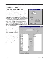
Page 104: ...ation edit booth etc A smaller console mounted version of this controller is designed for installation in Wheatstone consoles XP Configuration GUI The supplied Windows application XPoint is a password protected graphical user interface GUI which allows the user to configure monitor and control the 2001 digital audio network router The XP GUI communi catesusingTCP IPoverEthernettothe2001hostCPUcard...

Page 105: ...tware based method of controlling the Bridge 2001 utilizing a station s existing network infrastruc ture Multiple simultaneous users may connect signal sources to destinations and monitor the status of audio resources throughout a facility A signal visibility feature allows users to only see the resources on the router that pertain to their activities XY Rack Controller The XY Rack Controller is a...

Page 106: ...the XYR 1 pc board XY Meterbridge Mounted install jumpers J2 and J3 on the XYC 600 pc board XY 4 8 Module turn on positions 2 3 and 4 of dipswitch SW3 pos1 not used located on the XYC 700 pc board Setting an XY Controller Address All hardware XY controllers have a unique address from 1 to 64 that identifies their presence to the system This address is set via a pair of four position dipswitches mo...

Page 107: ...ter communications cable and is terminated with DB 9 male connectors on the both ends Typically one end of the cable plugs into the Serial Port A DB 9 female connector on the rear PWIH CPU rear or ONI panel OAN rear and the second end connects to either one of the two DB 9 female I O connectors on the rear of the XY Rack Controller or bottom of the console meterbridge for console mounted XY contro...

Page 108: ...eatstone consoles MUST be connected to serial ports configured as Console ports Cable Wiring XY Controller RS 485 cables are simple pin to pin cables It is important to use a high quality dual twisted pair cable suitable for extended distance data transmission A cable with an impedance of 125 ohms and nominal capaci tance of 12 8 pF ft 1 MHz is recommended See cable specifications and pinouts for ...

Page 109: ... taken Wheatstone console CPU modules connect to the 2001 Switch software viaadedicatedRS 485serialinterfacebus Notethatthisbusisseparatefrom and in addition to the XY controller bus Wheatstone Console RS 485 Connections Cables that are used for connecting a 2001 switcher RS 485 serial port to a Wheatstone console serial port are very similar to XY Controller RS 485 cables The only difference is t...

Page 110: ...nique numerical address e g 1 2 3 etc The console address is set via a bank of four position dipswitches located on the CPU module Refer to your console documentation for details or contact customer support RS 485 Select Termination The CPU module also has a pair of four position dipswitches that select the serial port mode and RS 485 termination Locate the RS 485 RS 232 Select dipswitch and set i...

Page 111: ...ition 4 8 Audio Network Card Definition 4 8 CPU Card Definition 4 9 Output Card Definition 4 9 Input Card Definition 4 10 Viewing Defined Source Destination Signals 4 10 Configuration Rules and Recommendations 4 11 Completing the Configuration 4 11 Saving Your Configuration 4 11 Config txt File 4 11 Signal Definition 4 14 Configuring Logic I O 4 15 Overview 4 15 Routable Logic 4 15 Trigger Port Lo...

Page 112: ...60 at the factory In order toconnectusingtheXPointsoftware thePCmusthaveamatchingnetworkprefix i e 192 168 1 xxx If your PC s current IP address does not match you must choose one of the following options change the IP address of the PC running the XPoint software or change the IP address of the Bridge 2001 router Changing your PC s IP Address To set your PC s IP address you must access the TCP IP...

Page 113: ... navigate to the Configure System menu item The following form will appear Important If you changed your PC s IP Address enter the parameters exactly as displayed above If you changed the Bridge 2001 s IP Address enter the parameters you entered using the Network Configuration Utility program If you are connected to the router you should see a Connecting to message in the status bar at the bottom ...

Page 114: ...eanddestinationsignalnaming XYcontrol ler mapping and optional Wheatstone console input channel mapping GUI Log In OncetheXPointsoftwarehasbeeninstalledandstarted a LogIn dialog box will be displayed on the screen There are three possible password protected log in identities that a user may log in as Guest Allows the user to view crosspoint status only No switching of I O signals XYC GUI Allows th...

Page 115: ...ns which may be downloaded later Assuming the default configuration files start the Configuration GUI in ON LINE mode a TCP connection to the Host CPU will be attempted as indicated via the status message and yellow status indicator shown below When the GUI successfully communicates with the Host CPU software it will start receiving the configuration that the Host CPU had stored in its nonvolatile...

Page 116: ...92 168 1 160 Tier1 Green Status Indicator Status Message Once the configuration has been uploaded the GUI enters the ONLINE state as shown to the left To disconnect from the Host CPU and go to OFF LINE mode select the View Mode Offline menu op tion The status indicator on the screen will then change as shown to the left ...

Page 117: ...above If the user made changes to a few crosspoints in OFFLINE mode and then goes to ONLINE mode the message box pops up Choose YES to save OFFLINE changes The 2001 software checks the request for validity input to output output not already assigned lock flag not set etc If the request is valid it is implemented and Configuration GUI is updated If not valid the request is rejected with an appropri...

Page 118: ...alledinrack s andattachedtothe Ethernet network This is done by selecting the Configure System menu option and the following Tier Configuration form appears Select the Number of Tiers in the system For each Tier ID provide a Tier Name the IP address Switch Port and Broadcast Port used The Number of Tiers IP Address Switch Port and Broadcast Port values must match the current settings of the Host C...

Page 119: ...location cabling and jumpering requirements StartuptheConfigurationGUIandlogintothesoftwareasAdministrator Select the Configure Rack Defs menu option The following form appears Adding a Card to a Rack Use the Tier ID and Rack ID spin edit fields to select a rack in the system Click on the appropriate slot in the rack to add a piece of hardware A pop up menu will appear with a list of available car...

Page 120: ...t properties are used to define the con figuration for the two serial ports sup ported by the Audio Network cards Port 1 and Port 2 refer to the serial portslabelledasPort AandPort Bon the ONI 2001 rear panel of the Audio Network card When assigning a port to a Virtual Serial Bus VSB make sure to set the Master Slave fields correctly depending on the types of devices connected to that port The Aud...

Page 121: ...0 Port 2 Consoles 9600 See the Host CPU section in the Hardware section of this manual for details on RS 485 serial communi cations wiring Output Card Definition If the selected card is an output card the form at the right appears after left clicking on the output card in the RackDefs form Click on the button labelled Card Definitions to modify the output card parameters The following form will ap...

Page 122: ...ion Signals The Card Properties form provides a way to quickly determine which signals have been mapped to a particular input or output card and if any spare audio channels are available Select the Configure Rack Defs menu option to view a given rack You may now query any input or output card by right clicking on its location A form similar to the one on the right will be displayed showing all sig...

Page 123: ...erconfiguration AudioNetworkcardsareusedtoconnect eachSatellitetiertotheHubtier Alltheseinterconnectingcardsmustreside in local racks in each tier In addition one interconnecting Audio Network card in each Satellite tier should reside in Rack ID 1 Slot 1 Completing the Configuration When all hardware has been added in this manner press Apply on the menu The GUI will validate and complete the confi...

Page 124: ...y this card 3 Diagnostics Info Proxy TDM ID used by this card 3 Rack 1 Slot 6 Analog Output Diagnostics Info OB used by this card 4 Diagnostics Info Proxy Block ID used by this card 4 Diagnostics Info hardwireTDM used by this card 1 Rack 1 Slot 7 Analog Output Diagnostics Info OB used by this card 3 Diagnostics Info Proxy Block ID used by this card 3 Diagnostics Info hardwireTDM used by this card ...

Page 125: ...nfo OB used by this card 7 Diagnostics Info OB used by this card 8 Rack 1 Slot 14 AES Output Diagnostics Info OB used by this card 2 Diagnostics Info Proxy Block ID used by this card 2 Diagnostics Info hardwireTDM used by this card 1 Rack 1 Slot 15 AES Output Diagnostics Info OB used by this card 1 Diagnostics Info Proxy Block ID used by this card 1 Diagnostics Info hardwireTDM used by this card 1...

Page 126: ... 8 Character description of signal s location Audio Signal Type Choose Source or Destination Format Choose Logic I O Only Mono Stereo or 5 1 Surround Audio Signal Location Tab Defines the signal s physical location Tier Rack Slot Circuits Logic I O Tab Maps up to six routable logic port signals to the current audio signal Also used to define Logic I O signals only See the Configuring Logic I O sec...

Page 127: ...follows the duration of the input signal thus allowing for latched or momentary applications LIO Only Sources are typically cross connected to LIO Only Destinations but mapped logic signals may be cross connected to independent logic signals as long as the assigned logic functions match Mapped logic signals enable the user to automatically route up to six logic signals along with an audio source W...

Page 128: ...io Signal Location Tab Defines the audio signal s physical location Tier Rack Slot Circuits not used for Logic I O Only signals Logic I O Tab Maps up to six routable logic port signals to the current signal Enabled LIO 1 through 6 check to activate up to six LIO s Tier Rack Card identify physical location of logic card Port choose one of 12 available physical ports Direction In or Out selects inpu...

Page 129: ...he Define button in the lower right corner to open the Logic I O Types form shown below ID static value from 1 to 50 cannot be changed Use the up down arrows to scroll to the desired function num ber Name Be sure to assign each function a unique name to avoid potential confusion when mapping logic func tions Names may be up to 8 characters long Precedence always set to Controller for logic card ap...

Page 130: ...onfig ured as routable logic will ap pear to be grayed out The following form descrip tionincludesparametersthatmay be configured Input Port indicates which physical port is being config ured Salvo check boxes assigns input port to fire a salvo Salvo use drop down list ar row to select a Salvo to be fired Temporary Connection check boxes assigns input port to temporarily connect a source to a dest...

Page 131: ... D E Signal Locking To lock a signal right click on one of available output channels on the crosspoint grid and select Lock Connection That crosspoint output signal becomes locked as indicated by red line through the signal on the GUI display and shown on form below ...

Page 132: ...urce routed to a destination signal that has logic attached before routing the source to a new destination to avoid illegal logic state conditions Whencompleted theoperatorleavesSalvoEditMode atwhichpointthe newly defined Salvos are available for use If the application is connected to a switch ON LINE mode the new Salvo definitions are automatically sent to the switch It is a good idea to save the...

Page 133: ...ss is momentarily displayed on power up See the Hard ware chapter for addressing details if necessary Also decide whether each controller will have ac cess to the entire I O signal space View All or just a subset View Subset If a subset is selected the follow ing form will be displayed The next step is to set the Input Output and Salvo visibil ity options by choosing Input Output orSalvo Nexthighl...

Page 134: ...s to avoid unnecessary system communication latency Special Functions Console Locks If a crosspoint output signal is mapped to a console module and that module is ONAIR thatcrosspointoutputsignalbecomesconsole locked asindicated by a blue line through the signal on the GUI display When a signal is console locked its connection to a crosspoint input cannot be changed To change this connection take ...

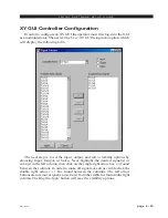
Page 135: ...xt step is to set the input output and salvo visibility options by choosing Input Output or Salvo Next highlight the desired signal s or salvo s in the left column then click on the single right arrow box found between the columns In order to make all signals or salvos visible click the double right arrow box found between the columns The left arrow buttonsaretoremovesignal s orsalvo s fromthevisi...

Page 136: ...ource destination signal visibility of this machine when logged in at the XYC access level Configure Menu System Configure TCP IP network and Host port parameters Rack Defs Define installed hardware parameters on a rack by rack basis Allows user to see define and configure all installed cage hardware Controller Configuration Used to define and configure hardware based XY controllers present in the...

Page 137: ...agnostics Menu View App Log Opens network communications activity log Can save log to a file for technical support purposes View Switch Status Lists all active installed hardware card firmware revisions Reset Switch Initiates a Host CPU reboot Use this function with caution ...

Page 138: ...oo eee referstotheWindowsXPointprogram Graphical User Interface XYC GUI refers to the XPoint program running in XY controller mode Master Rack The first rack in a 2001 Switch which must contain the controlling CPU for the switch Slot A position within a rack where a single card is located Tier A single 2001 switch which may consist of multiple remote and local chassis that are controlled by a sing...

Page 139: ...ing of Ø1 equals Rack ID 2 etc Slot ID The physical slot number in each chassis numbered from 1 22 Backplane wiring defines a card s slot ID A CPU card must be in Rack ID 1 Slot ID 22 TDM ID This indicates the TDM bus to be used There are up to 32 TDMs in each chassis labeled from 1 32 TDM Slot ID Within each TDM there are up to 16 discrete channels which each take up one slot within the TDM bus A...

Page 140: ...age A 1 2001 Jul 01 A P P E N D I C E S Appendix 1 Configuring the 2001 Switch Network Parameters A 3 Appendix 2 Failover CPU Configuration Operation A 6 Appendix 3 Replacement Parts List A 9 Appendices ...

Page 141: ...page A 2 2001 Jul 01 A P P E N D I C E S Appendix 1 Contents Configuring the 2001 Switch Network Parameters A 3 ...

Page 142: ...HCP the switch must be given a permanent address allocation In order to allow the switch to run on simple networks or at sites with little system admin support dynamic address allocation schemes such as DHCP or BOOTP were not used to provide an IP address to the switch The following steps are required to provide the necessary configuration info to the switch this only has to be done one time 1 Fro...

Page 143: ...e rare circumstance that it conflicts with another port in use on the GUI PC The default can almost always be used 9 The program then repeats the following prompt for each tier configured in step 2 About to configure Tier 1 1 Make sure this is the only tier currently connected to the local network 2 Press RETURN when ready to proceed The configuration parameters for the specified tier are now UDP ...

Page 144: ...page A 5 2001 Jul 01 A P P E N D I C E S Appendix 2 Contents Failover CPU Configuration Operation A 6 ...

Page 145: ...ination resistors removed must be installed for failover CPU operation In addition a terminator card must be installed in Slot 21 at the right end of the master chassis The primary CPU card will be installed in Slot 22 the backup CPU will be installed in slot 20 Ethernet Connections Both the primary and backup CPU cards must be connected via ethernet to the same network and subnet The CAT 5 cables...

Page 146: ...sspoint connections System control is transferred to theBackupCPUuponcompletionoftheconfigurationdump Switchrequests from hardware or software controllers which happen to occur during the transition time will be ignored and lost Master clock backplane signals are automatically switched to the originate from the backup CPU oscillator or optional AES sync thereby providing continuous operation of au...

Page 147: ...ceable parts in the 2001 Switch A complete list of available components is shown on the next page Contact Wheatstone technical support for further informa tion Wheatstone Corporation 600 Industrial Drive New Bern North Carolina USA 28562 may be reached by phone at 252 638 7000 fax 252 637 1285 electronic mail email wheatstone com ...

Page 148: ...340 DB 2001 COMPLETE REAR MODULE WITH ONE DB 25 CONNECTOR 008346 8BNC 2001 COMPLETE REAR MODULE WITH EIGHT BNC CONNECTORS 008345 8RJ 2001 COMPLETE REAR MODULE WITH EIGHT RJ 24 CONNECTORS 008344 ONI 2001 COMPLETE REAR MODULE FOR SERIAL INTERFACE CONNECTIONS 008343 PWIH 2001 COMPLETE REAR MODULE FOR SERIAL INTERFACE POWER SUPPLY CONNECTIONS 008341 PWI 2001 COMPLETE REAR MODULE FOR POWER SUPPLY CONNE...

Reviews: