page 2 – 35
2001 / Jul 01
H A R D W A R E
Switch Settings
DIPSW1-SW4 RS-485 Termination
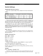
These four, 4-position dipswitches configure the 485 port termination as
follows:
Choices are Unterminated, Normal Termination, or BIAS Termination on
the transmit and receive lines. SW1 and SW2 are for Port A, and SW3 and
SW4 are for Port B. SW1 and SW3 are for the RS-485 transmitter’s
termination on the CPU; SW2 and SW4 are for receiver terminations.
An RS-485 bus may only be BIAS TERMINATED at one end. All
applicable Bridge 2001 OAN and CPU cards are set for BIAS TERMINA-
TION by default. All peripheral devices are set for NO TERMINATION by
default. Set the TERMINATION to ON for the last controller or console only,
in a RS-485 chain.
SW5 - CPU R
ESET
This momentary pushbutton switch allows CPU to be reset without power
down of system. Holding for two seconds will cause the FPGA to be
reprogrammed also.
DIPSW6 - Utility Switches
Pos.1 - DIP4 - not used
Pos.2 - DIP5 - not used
Pos.3 - C6 - not used
Pos.4 - C7 - not used
DIPSW7 - Rack ID
Default is all OFF (Rack ID 1, binary ØØØØ) for a master rack CPU.
Note: Rack ID numbers are coded in binary.
Rack ID 1 equals binary Ø‚ Rack ID 2 equals binary 1, etc.
Rack ID’s are set at the factory. Incorrect setting of these switches can cause
system malfunction.
DIPSW8
Pos.1 - Autodetect - default is “ON”
Autodetect will sense the presence of an external AES input clock and
slave the system to this AES reference. If the AES reference fails (wire breaks,
POSITION
BIASED TERM
PASSIVE TERM
UNTERMINATED
1 - TX10
Ω
2 - TX+
3 - TX-
4 - 120
Ω
OFF*
ON*
ON*
ON*
ON
OFF
OFF
ON
OFF
OFF
OFF
OFF
SW1-SW4
FUNCTION
ON=10
Ω
BYPASS
ON=750
Ω
PULLUP
ON=750
Ω
PULLDOWN
ON=120
Ω
PARALLEL
2001 / Apr 03


