page 2 – 38
2001 / Jul 01
H A R D W A R E
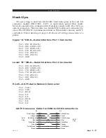
Hook-Ups
All user wiring to and from CPU card takes place at the rear I/O connector
module (PWIH-2001) that plugs into the extreme left-hand slot (if you are
looking at the rear of the cage). There are three DB-9 female serial interface
connectors, one RJ-45 Ethernet connector and two power supply connectors.
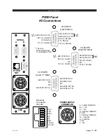
Pinout drawing on page 2-40 shows all wiring connections at a glance.
L
EFT
“A” DB-9—S
ERIAL
I
NTERFACE
P
ORT
1 C
ONNECTIONS
P
IN
5 – AES SYNC O
UT
SH
P
IN
4 – AES SYNC O
UT
HI N
OT
U
SED
P
IN
9 – AES SYNC O
UT
LO
P
IN
3 – RX1 HI (RS-485)
P
IN
8 – RX1 LO (RS-485) / GND (RS-232)
P
IN
2 – TX (RS-232)
P
IN
7 – RX (RS-232)
P
IN
1 – TX1 HI (RS-485)
P
IN
6 – TX1 LO (RS-485)
R
IGHT
“B” DB-9—S
ERIAL
I
NTERFACE
P
ORT
2 C
ONNECTIONS
P
IN
5 – AES SYNC I
N
SH
P
IN
4 – AES SYNC I
N
HI N
OT
U
SED
P
IN
9 – AES SYNC I
N
LO
P
IN
3 – RX2 HI (RS-485)
P
IN
8 – RX2 LO (RS-485)
P
IN
2 – N/C
P
IN
7 – N/C
P
IN
1 – TX2 HI (RS-485)
P
IN
6 – TX2 LO (RS-485)
L
OWER
“C” DB-9—AES SYNC P
ORT
C
ONNECTIONS
P
IN
5 – AES SYNC I
N
SH
P
IN
4 – AES SYNC I
N
HI
P
IN
9 – AES SYNC I
N
LO
P
IN
2 – AES SYNC O
UT
SH
P
IN
1 – AES SYNC O
UT
HI
P
IN
6 – AES SYNC O
UT
LO
RJ-45—E
THERNET
C
ONNECTIONS
P
IN
1 – TXD +
P
IN
2 – TXD -
P
IN
3 – RXD +
P
IN
4 – N/C
P
IN
5 – N/C
P
IN
6 – RXD -
P
IN
7 – LN LED
P
IN
8 – LK LED
2001 / Nov 02

